
Pneumatic reset relief valve

a technology of pneumatic reset and valve, which is applied in the direction of valve operating means/releasing devices, functional valve types, service pipe systems, etc., can solve the problems of equipment connected, costly damage to the pump itself,

Inactive Publication Date: 2005-07-19
NAT OILWELL VARCO LP
View PDF20 Cites 12 Cited by
  • Summary
  • Abstract
  • Description
  • Claims
  • Application Information

AI Technical Summary

Benefits of technology

[0006]The present invention functions as a safety device to protect a mud pump from an over pressure situation, which can occur during normal operation. Over pressuring the mud pump can cause costly damage to the pump itself, and equipment connected to the pump.

Problems solved by technology

Over pressuring the mud pump can cause costly damage to the pump itself, and equipment connected to the pump.

Method used


Image

  • Pneumatic reset relief valve
  • Pneumatic reset relief valve
  • Pneumatic reset relief valve

Examples


Embodiment Construction

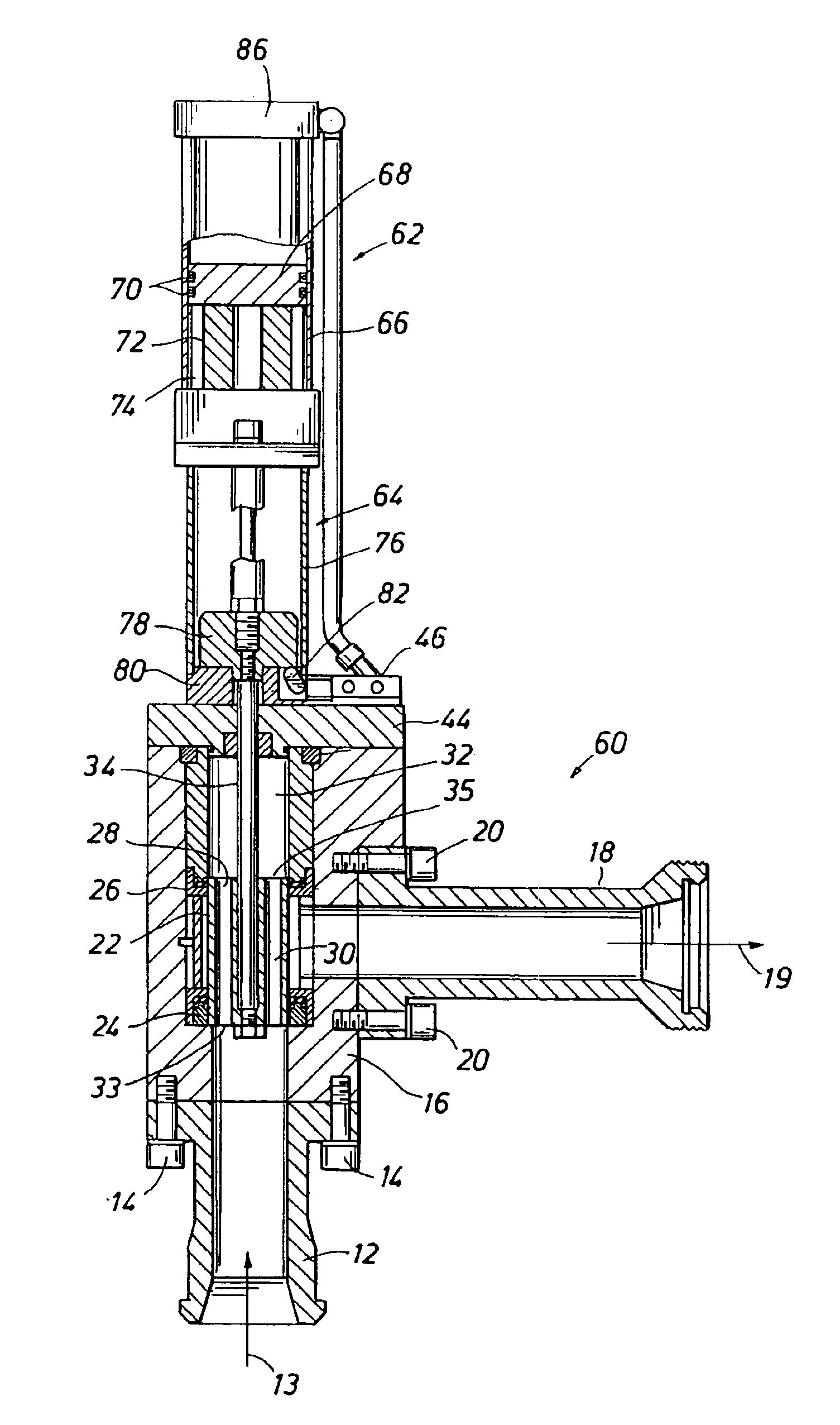
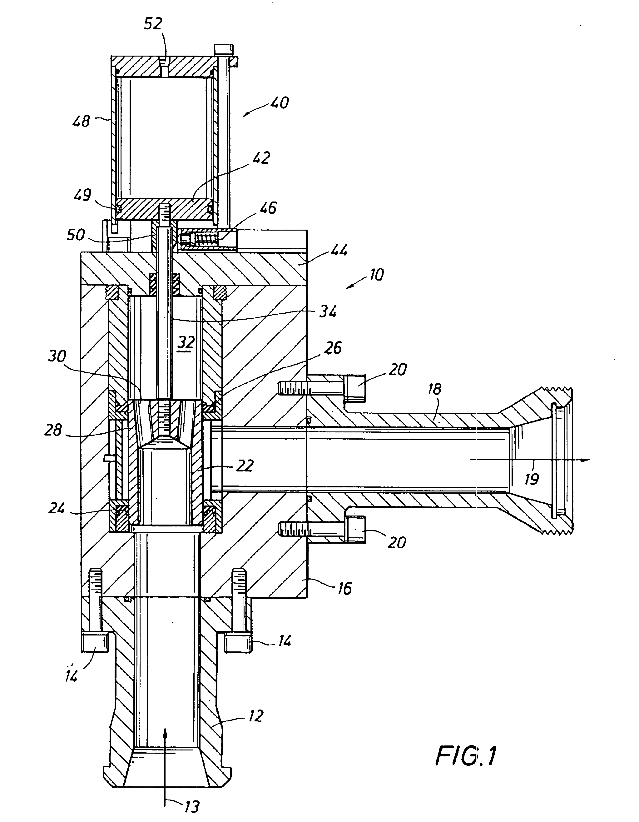
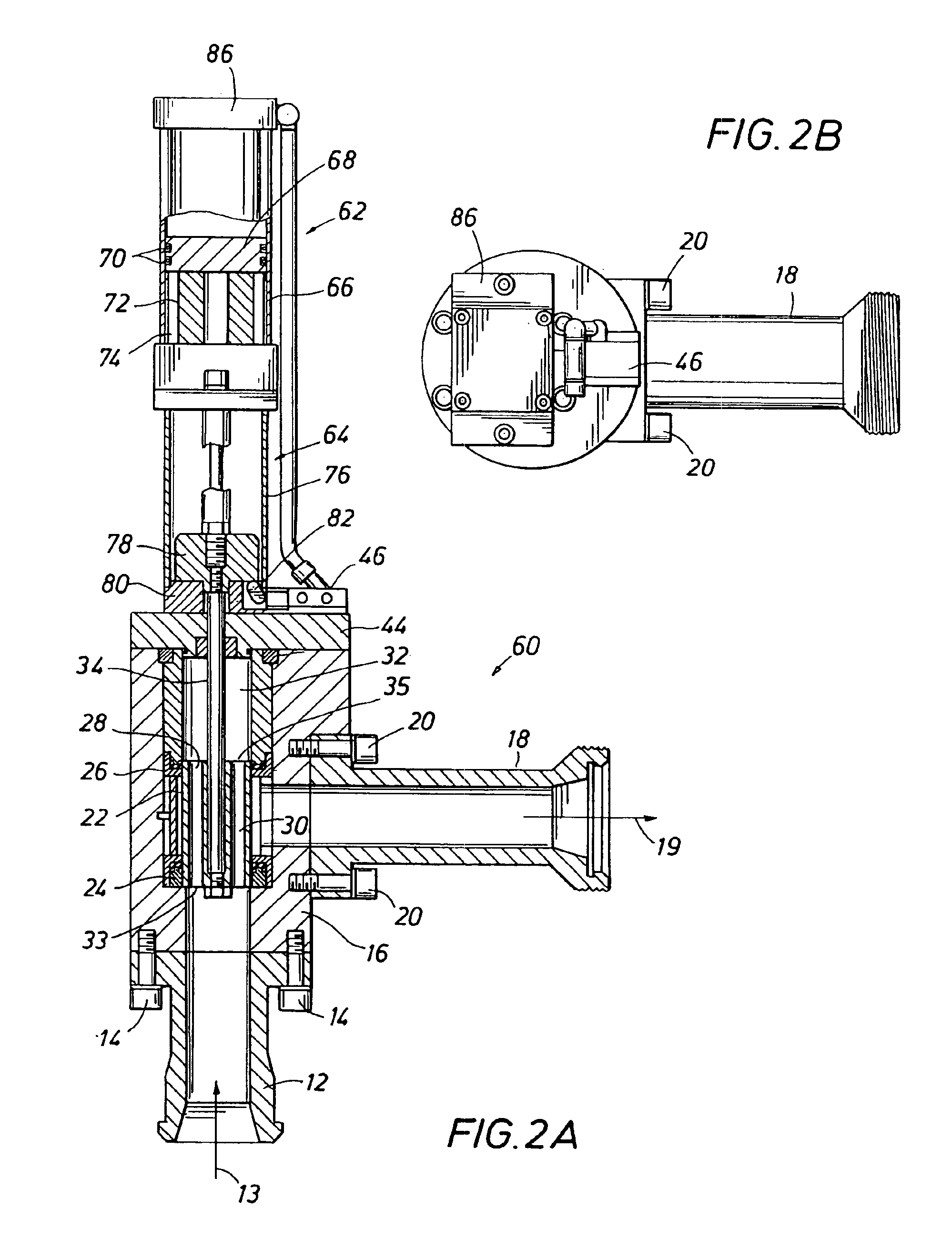
[0012]Referring now to FIG. 1, a pressure relief valve 10 constructed in accordance with this invention is depicted. Discharge pressure from a mud pump (not shown) is directed into an inlet 12 as shown by an arrow 13. The inlet 12 is bolted by bolts 14 to a valve body 16. Upon an over pressure condition and actuation of the relief valve, discharge is directed from a discharge or outlet port 18, as shown by an arrow 19. The discharge 18 is bolted to the body 16 with bolts 20.

[0013]Positioned within the body 16 is a load piston 22. The load piston 22 is sealed with a lower seal element 24 and an upper seal element 26, both of which remain stationary as the load piston moves up and down in response to variations in mud pressure at the inlet 12. The load piston 22 includes a top bulkhead 28, through which are at least two ports 30. The ports 30 conduct pressure into an upper chamber32, and thus the fluid pressure in the upper chamber tracks the pressure at the inlet 12. However, surface...


PUM


Abstract

A safety device protects a mud pump from an over pressure condition, which can occur during normal operation. The mud pump discharge couples to a high pressure inlet at the bottom of a valve body and the discharge outlet from the valve discharges to the side of the body, ninety degrees to the inlet. In a first aspect, the safety device includes a load piston mounted to a shaft which passes through a pressure chamber cap and connects to a pneumatic cylinder assembly on the top side of the pressure chamber cap. The pneumatic cylinder assembly is operated by a control valve mounted to the base of the cylinder to set the pressure at which the safety device actuates. In a further aspect, the safety device includes a light transmissive indicator cylinder, with a flag therein mounted on a rod coupling the valve to a pneumatic actuator piston, between the actuator piston and the valve.

Description

[0001]This application claims the benefit of U.S. Provisional application Ser. No. 60 / 310,965 filed Aug. 8, 2001.FIELD OF THE INVENTION[0002]The present invention relates generally to the field of pressure relief valves and, more particularly, to a pressure relief valve specially adapted for use with a positive displacement mud pump, the relief valve having a pneumatic reset feature.BACKGROUND OF THE INVENTION[0003]The present invention provides a pressure relief valve adapted to relieve an overpressure condition at the discharge of a mud pump. A mud pump, typically a triplex pump, delivers a large volume of mud flow for a drilling rig. The mud pump delivers drilling mud to the drill stem to flow down the string of drill pipe and out through the drill bit appended to the lower end of the drill stem. Then, the mud flow returns to the surface for recycling. To carry out its various functions, mud must flow at a substantial flow rate. A mud pump commonly delivers 1,000 gallons per minu...

Claims


Application Information

Patent Timeline
Patent Type & Authority Patents(United States)
IPC IPC(8): F16K17/02
CPCF16K17/02Y10T137/7853Y10T137/8225Y10T137/8359
Inventor WHITE, CHRISWILLIAMS, RICHARD D.
Owner NAT OILWELL VARCO LP
Learn More