[0106]The present invention overcomes the problems confronted by the sprinkler industry by advancing a cost effective trigger assembly which utilizes no glass or fluid components, which is direct loaded, and includes a minimum number of components to reduce the cost and complexity of manufacturing. Although the trigger assembly of the present invention may be used in conjunction with any sprinkler head, it is particularly suited for use in conjunction with quick response sprinkler heads, as its configuration results in a thermal sensitivity sufficient to classify the sprinkler head as quick response.
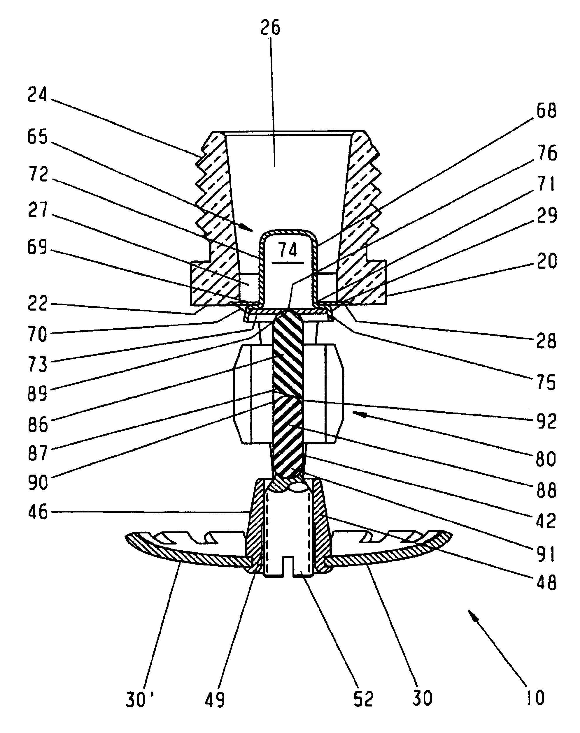
[0107]According to one aspect of the invention, a trigger assembly for an automatic sprinkler head includes a compression element positioned between a frame and a sealing assembly of the automatic sprinkler head. The trigger assembly also includes a thermally sensitive element surrounding at least in part the compression element and joined at least in part to the compression element by a fusible material. The thermally sensitive element includes at least two portions, each of which includes an attachment section shaped to substantially correspond to at least a section of the compression element, at least one connection section projecting from the attachment section in a direction away from the compression element, and at least one fin projecting from the distal end of the at least one connection section. The fin has a portion thereof defining a plane which forms an angular relationship to at least a portion of the connection section. The thermally sensitive element enhances the magnitude of compression of the compression element when joined thereto, and releases the sealing assembly when the thermally sensitive element is removed from the compression element. The fins of the thermally sensitive element increases the strength of the trigger assembly and the efficient retention and transportation of heat to the fusible material, which in turn increases the thermal sensitivity of the sprinkler head.
[0108]According to another aspect of the invention, a trigger assembly for an automatic sprinkler head comprises a compression element positioned between a sealing assembly and a
compression member of the sprinkler head which is mounted on a frame of the sprinkler head to adjustably exert compression on the trigger assembly. The compression element extends longitudinally with respect to the frame of the sprinkler head and has a center axis. The compression element is inherently unstable when subjected to a compressive force along its center axis by adjustment of the
compression member. The trigger assembly also includes a thermally sensitive element, which has an attachment section surrounding at least a portion of the compression element and is joined at least in part to the compression element by a fusible material. The thermally sensitive element is configured to maintain the compression element in a stable position between the compression member and the sealing assembly when the fusible material is below the fusing temperature and release the compression element to an unstable condition when the fusible material is above the fusing temperature. Additionally, the thermally sensitive element has at least one heat gathering member spaced from the attachment section. The heat gathering member defines at least one plane which is not co-planar with a plane defined by the center axis of the compression element. The combination of a compression element which is inherently unstable unless maintained in position by a thermally sensitive element eliminates the need for the use of a glass
bulb trigger assembly. Furthermore, the heat gathering member spaced from the attachment section of the thermally sensitive element increases the heat receptive surface area, and results in a trigger assembly having a faster
response time.
[0109]According to yet another aspect of the invention, a quick response sprinkler head comprises a sprinkler body having a central orifice defining a fluid outlet. A sealing assembly releasably seals the outlet to prevent fluid flow through the outlet, while a frame extending from the sprinkler body beyond the outlet carries a boss having an aperture dimensioned to receive a compression member. A direct load trigger assembly for releasably retaining the sealing assembly at the outlet includes a compression element, which extends longitudinally with respect to the sprinkler head and has a first end abutting the compression member and a second end abutting the sealing assembly. A thermally sensitive element is attached, at least in part, to the exterior of the compression element by a fusible material and has an attachment section surrounding at least a section of the compression element, at least one heat gathering member extending in a direction away from the compression element, and at least a portion forming a plane angularly related to the longitudinal axis of the compression element. The thermally sensitive element maintains the compression element in compression between the compression member and the sealing assembly when the fusible material is below the fusing temperature. Employing a heat gathering member spaced from the attachment section of a thermally sensitive element exposes the trigger assembly to a greater quantity of heat and thus decreases the
response time index of the sprinkler head.
[0110]According to still yet another aspect of the invention, a quick response sprinkler head includes a sprinkler body having a central orifice forming an outlet, a frame extending from the sprinkler body and beyond the outlet, and a compression member movably mounted to the frame. An externally activated direct load trigger assembly is disposed between the compression member and the sealing assembly and releasably retains the sealing assembly at the orifice outlet and has a response
time index (RTI) of less than, or equal to, approximately 90 (ft·s)1 / 2[50 (meters—second)1 / 2]. Providing an externally activated direct load trigger assembly having a response
time index of less than, or equal to, approximately 90 (ft·s)1 / 2[50 (meters—second)1 / 2] greatly reduces the manufacturing costs associated with a quick response sprinkler head by eliminating the reliance on glass
bulb trigger assemblies.
[0112]According to yet another aspect, the quick response sprinkler head has a RTI value equal to or less than approximatey 90(ft·s)1 / 2[50(m·s)1 / 2] and a C factor equal to or less than 1.8(ft·s)1 / 2[1.0(m·s)1 / 2], and complies with the criteria outlined in Section 4.30 of Approval Standard, Automatic Sprinklers for
Fire Protection, Factory Mutual Research Corporation, May 1998. Providing a sprinkler head which satisfies the criteria promulgated by various industry recognized organizations, and employs an externally activated, direct load trigger assembly greatly reduces manufacturing costs, while enabling the sprinkler head to be classified as quick response.


