Gasket

a gasket and gasket technology, applied in the field of gaskets, can solve the problems of unstable welding joint and disadvantageous sealing capacity of gaskets, and achieve the effect of limited flattening

Inactive Publication Date: 2005-07-19
REINZ DICHTUNGS +1
View PDF22 Cites 17 Cited by
  • Summary
  • Abstract
  • Description
  • Claims
  • Application Information

AI Technical Summary

Benefits of technology

[0022]One variant of the method according to the invention in which, when generating the welding bead in the metal layer, at least one sealing bead is generated in the metal layer, is especially time-saving since both can be done during one step. In this case, generating the welding beads and the sealing beads in the metal layer can be performed simultaneously or successively.
[0023]Additionally, it is provided in a preferred variant of the method that the current necessary for generating the projection welding joint is provided by discharging a capacity. This realization is the easiest possibility of generating a current rush having a high current within a short period of time.
[0024]Finally, when generating the welding joint, the flattening of the welding bead and thus the distance between the metal layer and the metal ring can be influenced by at least one deformation limiter within the welding bead or at least one abutment element outside the welding bead. The pressure acting on the metal layer and the metal ring during the welding process due to the welding electrodes involves a flattening of the welding bead. By using the deformation limiter and / or the abutment element according to the invention, this flattening is limited. The height of the deformationlimiter and / or the abutment element to a great extent determines the distance between the metal layer and the metal ring after generating the welding joint.

Problems solved by technology

Practice has shown that in gaskets which have been manufactured according to the described method, the metal ring and the metal layer can become detached which means that the welding joint is not stable.
This effect is disadvantageous for the sealing capacity of the gasket.

Method used


Image

  • Gasket
  • Gasket
  • Gasket

Examples


Embodiment Construction

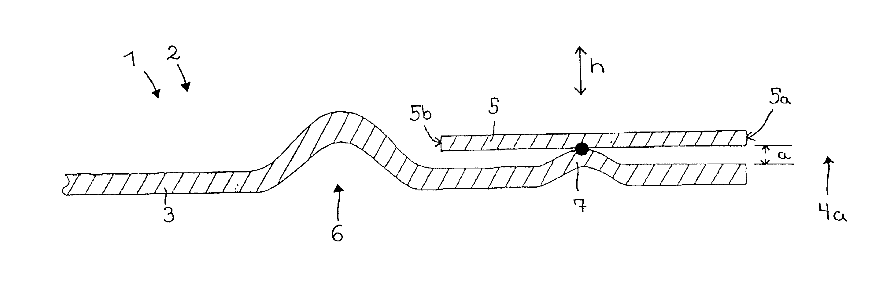
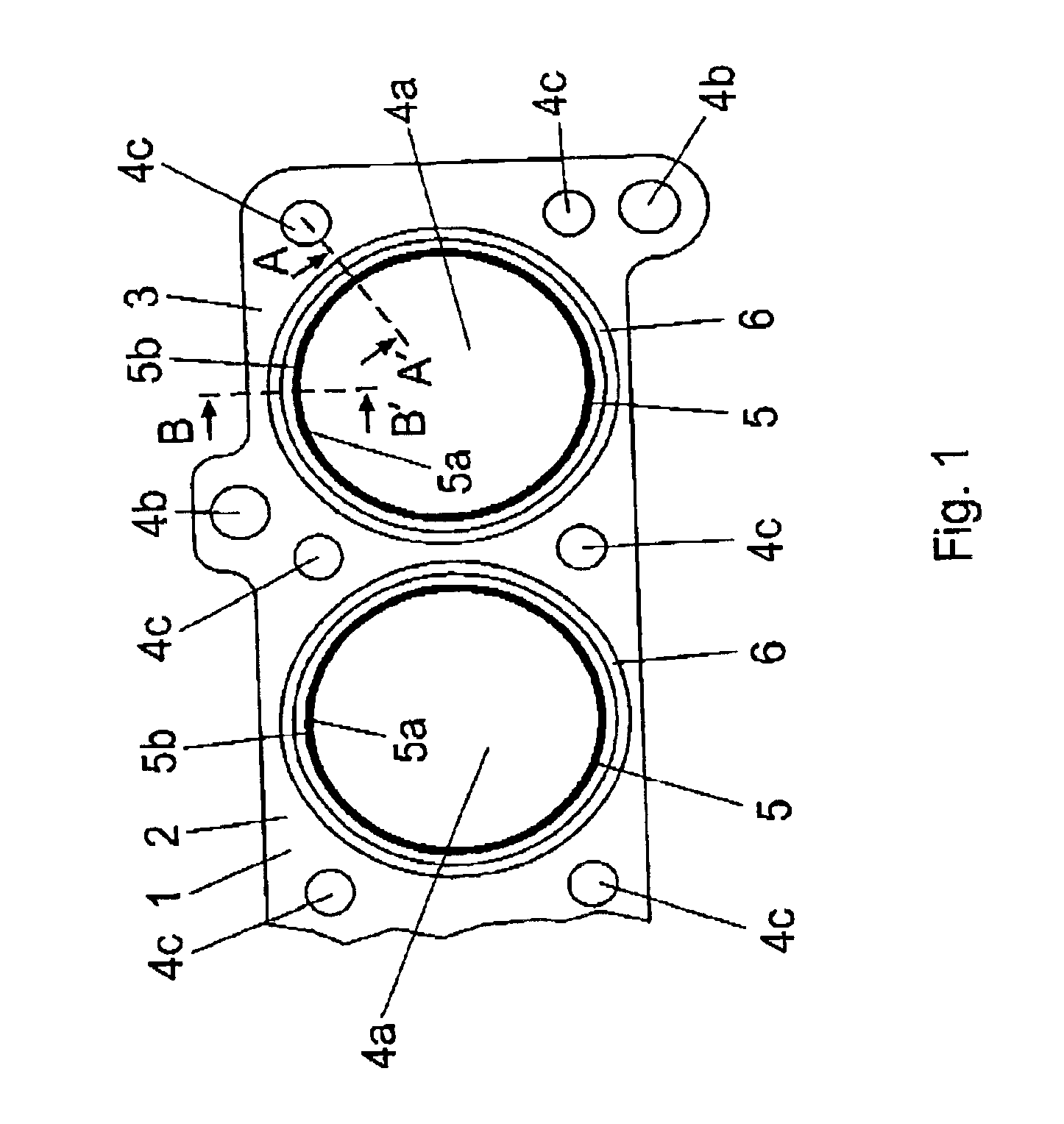
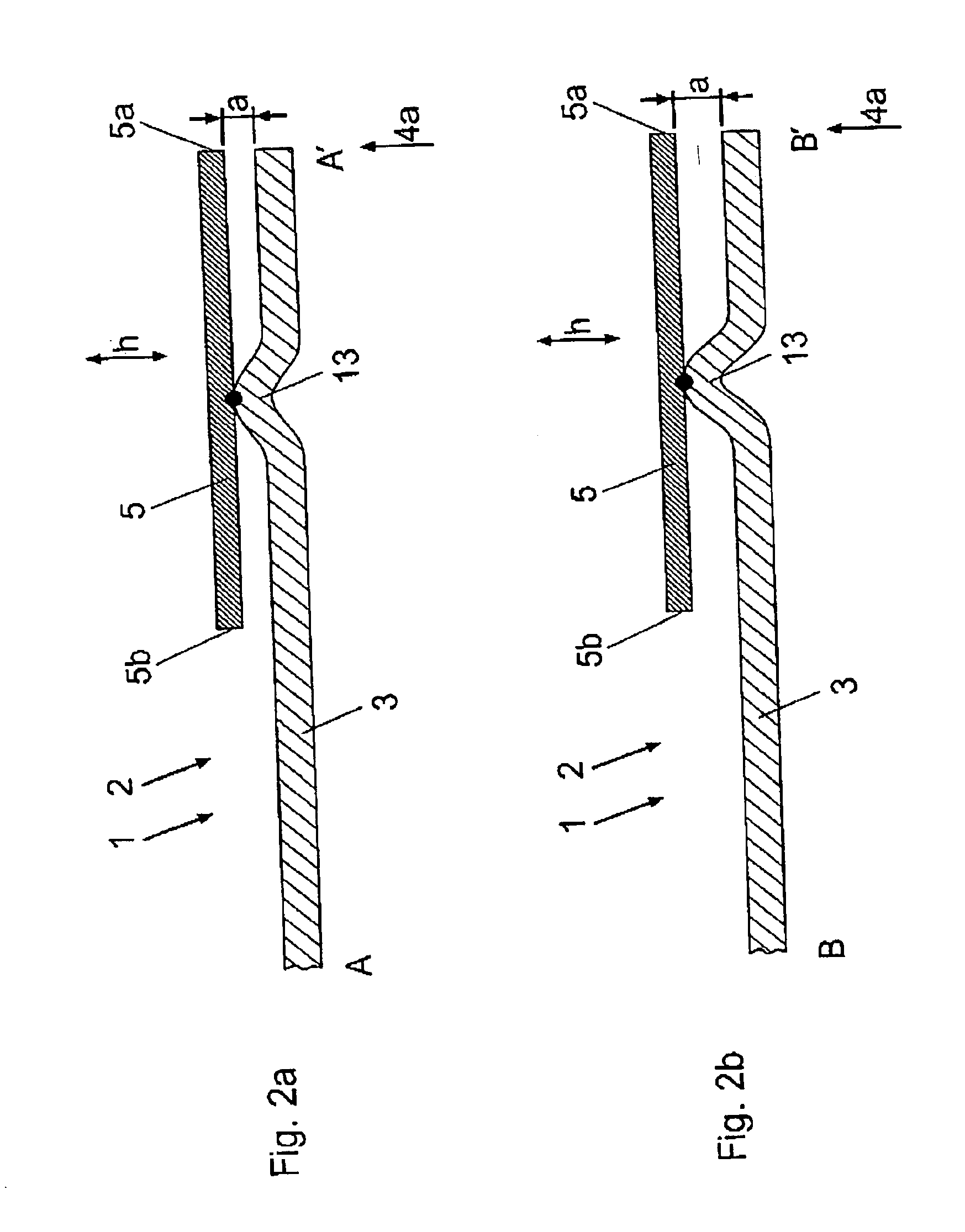
[0035]FIG. 1 shows a metal gasket 1 which is realized as cylinder head gasket 2. The gasket 1 is arranged between a cylinder head (not depicted) and a cylinder block (not depicted either) of an internal combustion engine. The gasket 1 comprises several adjacently arranged metal layers 3. In FIG. 1, only the uppermost metal layer 3 is visible. Each metal layer 3 comprises a plurality of through-holes 4. The metal layers 3 are arranged such that the through-holes 4 lie congruently with respect to each other.

[0036]The through-holes 4 are realized as through-holes 4a, 4b and 4c, wherein the through-hole 4a is assigned to the combustion chambers of the internal combustion engine, the through-hole 4b is assigned to the coolant and lubricant passageways of the internal combustion engine, and the through-hole 4c is assigned to the attaching means passageway of the internal combustion engine.

[0037]Around each through-hole 4a, a metal ring 5 is arranged. The metal ring 5 has an internal circu...


PUM

PropertyMeasurementUnit
heightaaaaaaaaaa
heightaaaaaaaaaa
heightaaaaaaaaaa

Abstract

The invention refers to a gasket (1), the gasket having at least one metal layer (3) and at least one metal ring (5) welded thereto, the metal layer (3) having at least one through-hole (4) and the metal ring (5) being arranged around the through-hole, (4). The metal layer (3) and the metal ring (5) are welded to each other along a welding bead (7) which keeps the metal layer (3) and the metal ring (5) in a spaced apart relationship to one another. The gasket (1) has welding joints which are stable for a long time, and thus a high sealing capacity.

Description

RELATED APPLICATION[0001]The subject matter of this application is related to application Ser. No. 09 / 848,206 filed May 4, 2001, in the name of Kurt HOHE et al., entitled “Gasket and Method for the Manufacture Thereof”.FIELD OF THE INVENTION[0002]The invention relates to gaskets, particularly but not exclusively gaskets of a type having at least one metal layer and at least one metal ring welded thereto, the metal layer having at least one through-hole and the metal ring being arranged around the through-hole. The invention also relates to a method for manufacturing gaskets.BACKGROUND OF THE INVENTION[0003]Nowadays, gaskets are used in many technical fields. One of those fields comprises internal combustion engines where the gaskets are used as cylinder head gaskets. In this case, the gaskets are arranged between the cylinder head and the cylinder block of the internal combustion engine. Combustion chambers, coolant and lubricant passageways and passageways for attaching means which...

Claims


Application Information

Patent Timeline
Patent Type & Authority Patents(United States)
IPC IPC(8): B23K11/11F02F11/00F16J15/08
CPCB23K11/115F02F11/002F16J15/0818F16J15/0825B23K2201/16F16J2015/085F16J2015/0862F16J2015/0875Y10S277/922B23K2101/16
Inventor EGLOFF, GEORG
Owner REINZ DICHTUNGS
Why Eureka
Try Eureka