Vertical cable management system with ribcage structure

a management system and vertical cable technology, applied in the direction of cables, cables, instruments, etc., can solve the problems of congestion of cabling and connectors, difficulty in managing cabling and demarcation and patching points, and difficulty for local area networks of structured connectivity communications systems

Inactive Publication Date: 2005-07-19
COMMSCOPE TECH LLC
View PDF18 Cites 85 Cited by
  • Summary
  • Abstract
  • Description
  • Claims
  • Application Information

AI Technical Summary

Benefits of technology

[0006]Another aspect of the present invention relates to a cable management device for use with a telecommunications equipment rack. The cable management device includes a generally planar spine section extending in a longitudinal direction, and mounting holes for receipt of fasteners to mount the planar spine section to the rack. First and second sets of ribs extend from the planar spine section in opposite directions, each opposite direction transverse to the longitudinal direction. Each rib has a main portion extending parallel to the planar spine section and transversely to the longitudinal direction, the main portion shaped in a manner to provide edge protection to cables and wires passing between the ribs. An intermediate portion is located at the distal end of the main portion. At least one of the sets of ribs includes a tab at the end of the intermediate portion extending transversely to the main portion.

Problems solved by technology

Suppliers and users of structured connectivity communications systems in local area networks often have difficulty managing the cabling and demarcation and patching points such as in communications closets and computer rooms.
Here, large numbers of data, voice, and video communications circuits, cables and connectors may be concentrated into small areas on relay racks and in communications cabinets resulting in congestion of cabling and connectors.

Method used


Image

  • Vertical cable management system with ribcage structure
  • Vertical cable management system with ribcage structure
  • Vertical cable management system with ribcage structure

Examples


Embodiment Construction

[0039]The cable management systems of the present invention allow for management of cable in and around telecommunications equipment racks and cabinets. The telecommunications cable may be fiber optic-based, copper-based, and combinations thereof. The cable management system maintains and directs cables connected to the telecommunications equipment.

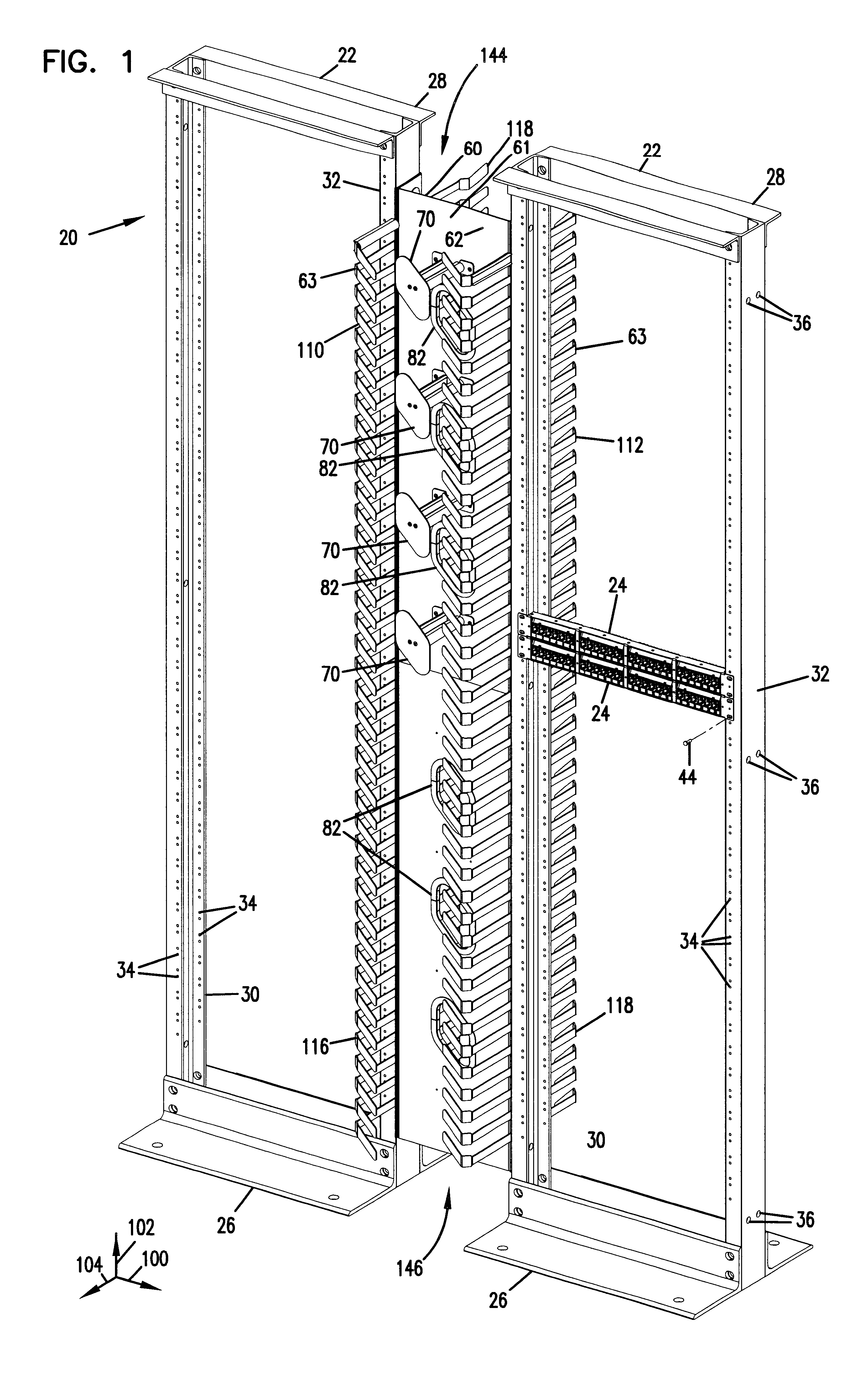
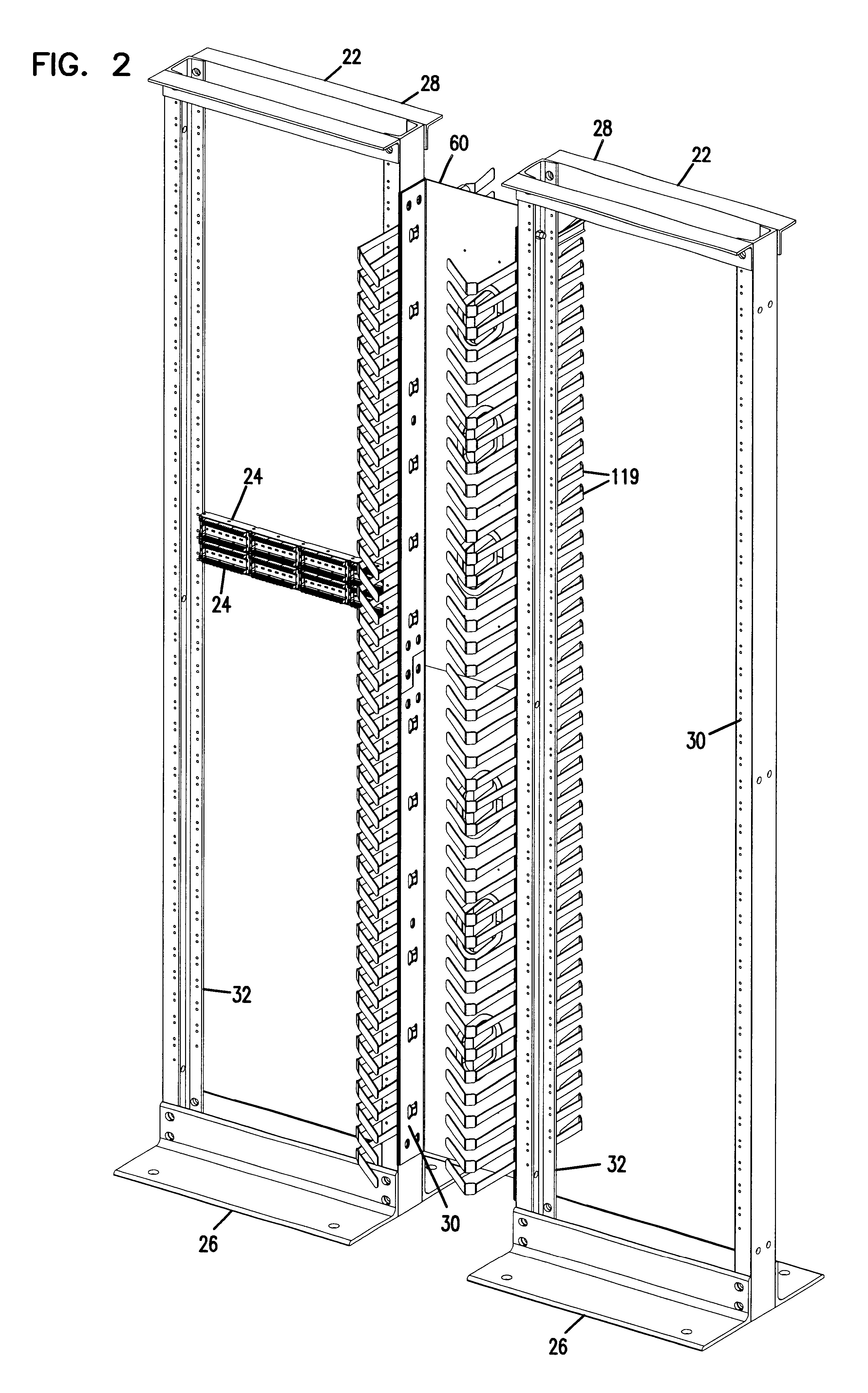
[0040]Referring now to the figures, one preferred embodiment of a cable management system 20 is shown including two vertical racks 22 configured and arranged for holding telecommunications equipment, such as a patch panel 24. Two patch panels 24 are shown in one of the racks 22. However, it is to be appreciated that additional patch panels 24, and other telecommunications connectivity equipment or cable management devices may be mounted to each of racks 22.

[0041]Each rack 22 includes a base 26, a top 28, and two side supports 30, 32 extending therebetween. Each side support 30, 32 includes a plurality of front and rear holes 34 for receiv...


PUM


Abstract

A cable management system (20) is provided including a rack (22) for holding telecommunications equipment (24), and a ribcage cable support member (60) along a vertical side of the rack. The ribcage cable support member includes a plurality of forwardly and rearwardly extending ribs (116, 118). The ribs each include cable retention tabs (124). A plurality of spools (70) are provided for cable storage on the ribcage cable support member. Holes (82) through the ribcage cable support member allow access between the front and rear portions. An additional rack may be positioned on an opposite side of the ribcage cable support member to the first rack, and two columns of ribs are provided. Resilient plastic edge protectors (150) may be fitted onto the ribs (119). The ribs may be shaped to provide integral edge protection.

Description

[0001]This application is a continuation-in-part of U.S. application Ser. No. 09 / 228,343, filed Jan. 11, 1999, now U.S. Pat. No. 6,468,112 the disclosure of which is incorporated herein by reference.FIELD OF THE INVENTION[0002]The present invention relates to cable management systems for telecommunications cables.BACKGROUND OF THE INVENTION[0003]Suppliers and users of structured connectivity communications systems in local area networks often have difficulty managing the cabling and demarcation and patching points such as in communications closets and computer rooms. Here, large numbers of data, voice, and video communications circuits, cables and connectors may be concentrated into small areas on relay racks and in communications cabinets resulting in congestion of cabling and connectors. In the past, connectivity systems attempted to ease the congestion of cabling and connectors by integrating cable management devices within and around the racks and cabinets. In the connectivity i...

Claims


Application Information

Patent Timeline
Patent Type & Authority Patents(United States)
IPC IPC(8): H04Q1/02H04Q1/06H04Q1/14H02G1/06G02B6/36H01R9/22H02G3/00
CPCG02B6/4452H01R9/2416H02G3/26H04Q1/062H04Q1/066H04Q1/13H04Q2201/02H04Q1/06
Inventor ELLIOT, DOUGLAS G.COPPOCK, DAVIDWALTERS, CINDY S.
Owner COMMSCOPE TECH LLC
Why Eureka
Try Eureka