
High-voltage transformer and discharge lamp driving apparatus

Inactive Publication Date: 2005-07-19
SUMIDA TECH +1
View PDF9 Cites 18 Cited by
  • Summary
  • Abstract
  • Description
  • Claims
  • Application Information

AI Technical Summary

Benefits of technology

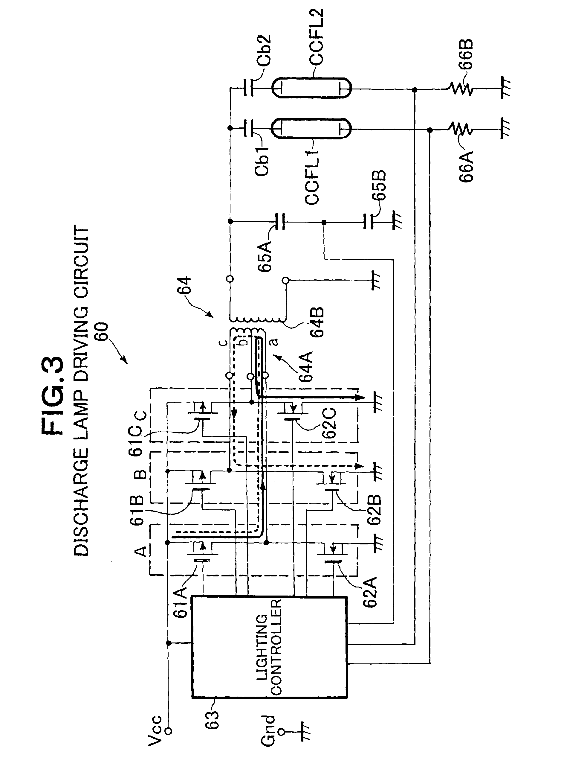
[0013]It is an object of the present invention to provide a high-voltage transformer with switchable secondary voltages and a discharge lamp driving apparatus, which can stably keep a plurality of discharge lamps lighting with a single transformer, improve the reliability of the transformer, and secure safety against the isolation voltage between turns of the secondary coil of the transformer and the like.

Problems solved by technology

Continuously outputting such a high voltage lowers the reliability of the transformer, thus making it difficult to secure safety against the isolation voltage between turns of the secondary coil in the transformer and the like.
However, the high-voltage transformer 610 has no function to regulate its voltage.

Method used


Image

  • High-voltage transformer and discharge lamp driving apparatus
  • High-voltage transformer and discharge lamp driving apparatus
  • High-voltage transformer and discharge lamp driving apparatus

Examples


Embodiment Construction

[0038]In the following, the high-voltage transformer in accordance with an embodiment of the present invention will be explained in detail with reference to the accompanying drawings.

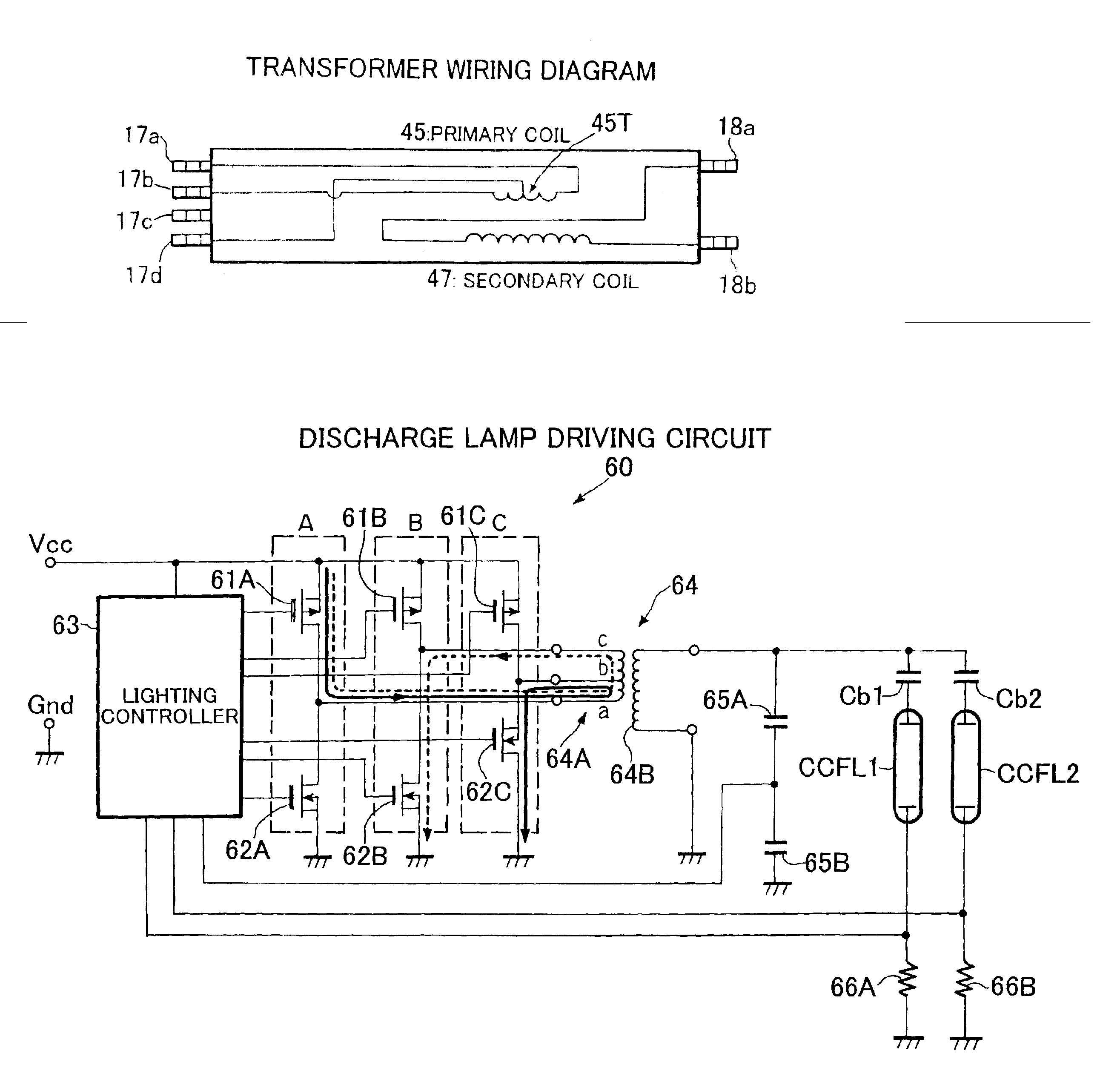
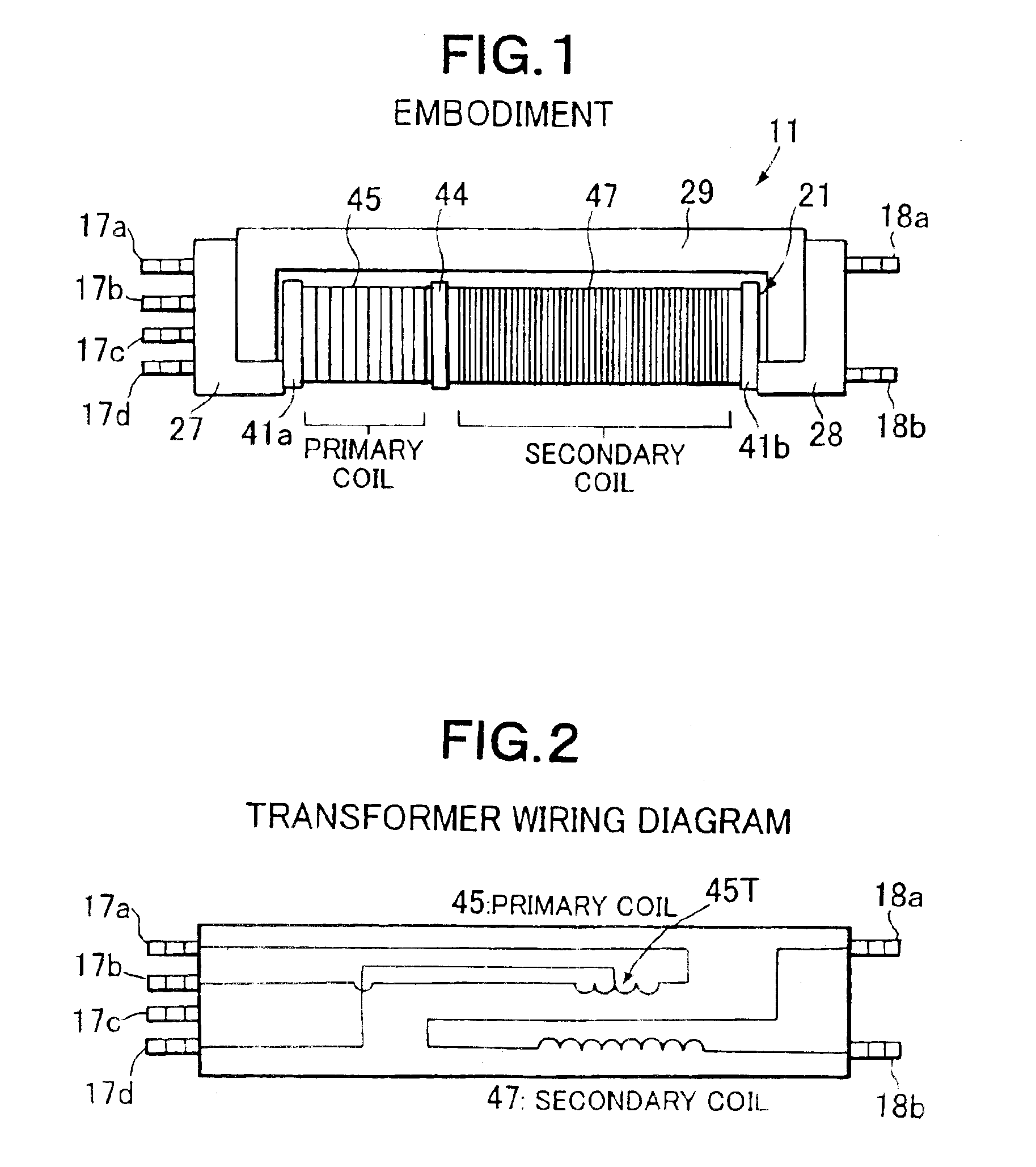
[0039]FIG. 1 is a plan view showing the exterior of the high-voltage transformer in accordance with an embodiment of the present invention, whereas FIG. 2 is a wiring diagram showing a characteristic concept of the high-voltage transformer.

[0040]The high-voltage transformer 11 in accordance with this embodiment shown in FIG. 1 is an inverter transformer used in a DC / AC inverter circuit for simultaneously discharging / lighting two CCFLs (cold cathode fluorescent lamps). Its primary coil 45 and secondary coil 47 are wound about a common rod-shaped magnetic core (hidden in FIG. 1) made of ferrite or the like which is a soft magnetic material, and are electromagnetically connected to each other by the common rod-shaped magnetic core.

[0041]An insulating partition 44 is disposed between the primary coil 45 and...


PUM


Abstract

A high-voltage transformer for lighting a plurality of discharge lamps has a primary coil for inputting an AC voltage and a secondary coil for outputting a predetermined AC voltage higher than the AC voltage inputted. The primary coil has a starter primary winding for initially lighting the discharge lamps, and a normal lighting primary winding for normally lighting the discharge lamps.

Description

RELATED APPLICATIONS[0001]This application claims the priority of Japanese Patent Application No. 2003-122486 filed on Apr. 25, 2003, which is incorporated herein by reference.BACKGROUND OF THE INVENTION[0002]1. Field of the Invention[0003]The present invention relates to a high-voltage transformer and a discharge lamp driving apparatus which are used, for example, in a lighting circuit of a discharge lamp for backlight in a liquid crystal display panel and, in particular, to a high-voltage transformer and a discharge lamp driving apparatus, used in a DC / AC inverter circuit, for simultaneously lighting a plurality of discharge lamps.[0004]2. Description of the Prior Art[0005]It has conventionally been known to discharge / light a plurality of cold cathode fluorescent lamps (hereinafter referred to as CCFLs) simultaneously as backlight for various liquid crystal display panels used in notebook PCs, for example. Using a plurality of CCFLs as such can respond to demands for higher lumina...

Claims


Application Information

Patent Timeline
IPC IPC(8): H05B41/282H05B41/28H01F27/28H05B41/24H02M7/538H05B41/23H05B41/231
CPCH05B41/2822H01F27/28
Inventor FUSHIMI, TADAYUKI
Owner SUMIDA TECH
Learn More