
Bioelectrode component

a bioelectrode and component technology, applied in the field of bioelectrode components, can solve the problems of inability to apply for a utility for obtaining correct information, and the influence of the electrode pad,

Active Publication Date: 2020-03-17
SHINKO ELECTRIC IND CO LTD
View PDF11 Cites 0 Cited by
  • Summary
  • Abstract
  • Description
  • Claims
  • Application Information

AI Technical Summary

Benefits of technology

The present invention provides a bioelectrode component that can prevent the needle part from separating from the biological surface during use. This ensures stable contact between the needle part and the surface, allowing for effective biological monitoring.

Problems solved by technology

Since the electrode pad in which the particles of Ag and AgCl are mixed with the gel phase resin is just contacted to a surface of the skin of the human body, the electrode pad is likely to be influenced due to a noise and cannot be thus applied for a utility for obtaining correct information of the human body.

Method used


Image

  • Bioelectrode component
  • Bioelectrode component
  • Bioelectrode component

Examples


first exemplary embodiment

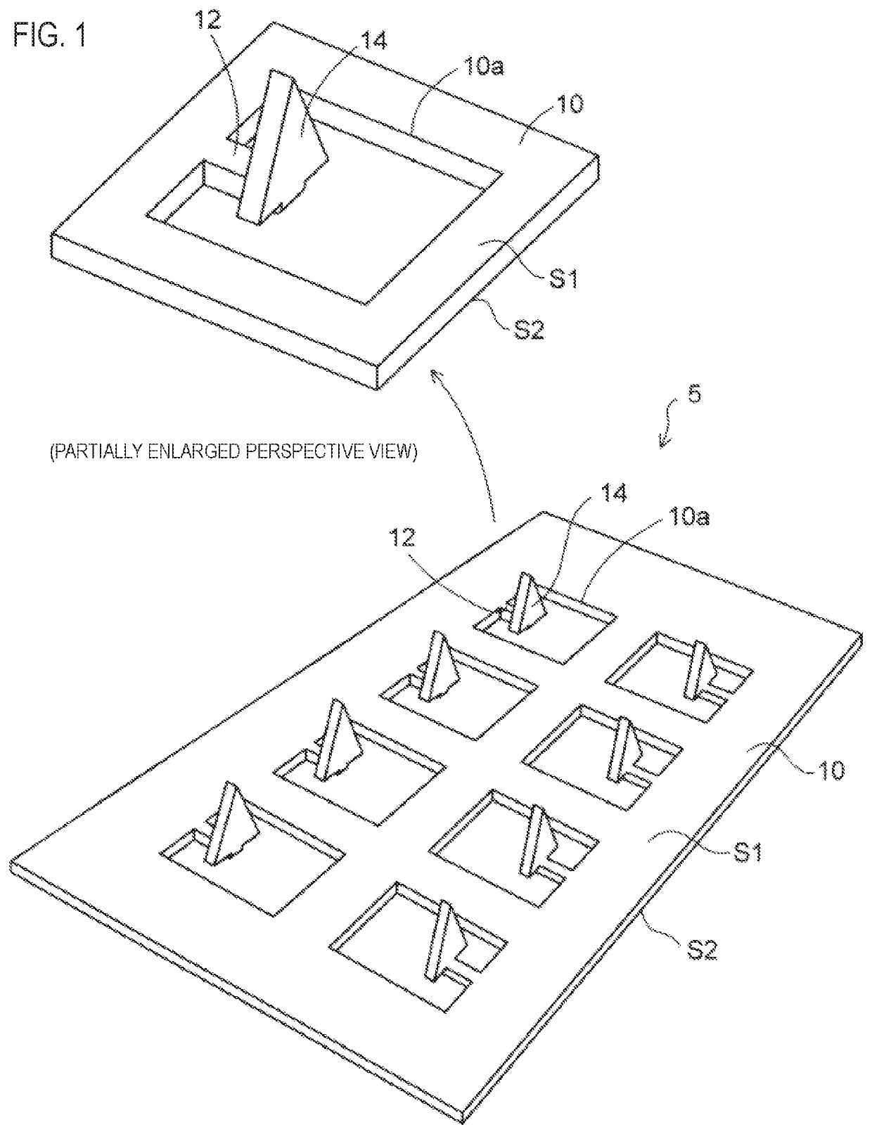
[0039]FIG. 1 is a perspective view depicting an electrode member of a bioelectrode component of a first exemplary embodiment. As shown in FIG. 1, an electrode member 5 that is used for a bioelectrode component of the first exemplary embodiment includes a thin plate-shaped metal plate 10, and the metal plate 10 is formed with a plurality of openings 10a. The opening 10a of the metal plate 10 is formed to penetrate the metal plate 10 in a thickness direction.

[0040]The metal plate 10 has a first surface S1 and a second surface S2 opposite to the first surface. In the example of FIG. 1, the first surface S1 of the metal plate 10 is an upper surface, and the second surface S2 is a lower surface.

[0041]As the metal plate 10, a metal foil made of titanium (Ti), nickel silver (copper (Cu) / zinc (Zn) / nickel (Ni) alloy) or the like is used. A thickness of the metal plate 10 is 0.05 mm to 0.1 mm, for example.

[0042]Referring to a partially enlarged perspective view of FIG. 1, the electrode member...

second exemplary embodiment

[0096]FIG. 11 is a perspective view depicting an electrode member of a bioelectrode component of a second exemplary embodiment. As shown in FIG. 11, an electrode member 5a that is used for the bioelectrode component of the second exemplary embodiment is different from the electrode member 5 of the first exemplary embodiment shown in FIG. 1, in terms of the shape of the needle part 14.

[0097]As shown in a partially enlarged perspective view of FIG. 11, the width W2 of the needle part 14 is set greater than the width W1 of the coupling bar 12. The needle part 14 has protrusions P protruding toward the second surface S2 (the lower surface) of the metal plate 10 at both end portions in the width W2 direction.

[0098]FIG. 12 is a sectional view taken along a line X3-X3 of the partially enlarged perspective view of FIG. 11. Referring to FIG. 12, the needle part 14 has a shape where a triangular shape having a sharp leading end and two rectangular protrusions P formed at both end portions of ...


PUM

PropertyMeasurementUnit
thicknessaaaaaaaaaa
length L2aaaaaaaaaa
thicknessaaaaaaaaaa

Abstract

A bioelectrode component includes an electrode member. The electrode member includes a metal plate, a coupling bar, and a needle part. The metal plate includes a first surface and a second surface opposite to the first surface, and includes an opening formed in the metal plate. The coupling bar extends inward from an inner wall of the opening. The needle part is arranged at a leading end of the coupling bar and protrudes toward the first surface of the metal plate.

Description

CROSS-REFERENCE TO RELATED APPLICATION[0001]The present application claims priority from Japanese Patent Application No. 2017-219641 filed on Nov. 15, 2017, the entire content of which is incorporated herein by reference.BACKGROUNDTechnical Field[0002]The present disclosure relates to an electrode component for a biological body (hereafter, referred to “bioelectrode component”).Related Art[0003]In the related art, biosignals such as electrocardiogram and brain wave are measured by bringing an electrode pad into contact with skin of a human body. As the electrode pad, a pad in which particles of Ag and AgCl are mixed with a gel phase resin is used.[0004]Also, a micro needle for hypodermic injection has been developed. In the micro needle, a plurality of small needle parts is provided on a sheet, and a layer of which skin is shallow is pierced with the needle parts, so that a medicinal agent such as vaccine is medicated into the skin and can reach an inside of the body.[0005]Patent Do...

Claims


Application Information

Patent Timeline
Patent Type & Authority Patents(United States)
IPC IPC(8): A61B5/0402A61B5/0408A61N1/30A61B5/0492A61M37/00A61B5/0478A61B5/296
CPCA61M37/0015A61B5/0492A61N1/303A61B5/0408A61B5/0478A61B5/0402A61M2037/0061A61M2037/0053A61B2562/125A61B2562/0209A61B5/25A61B5/291A61B5/296A61B5/318
Inventor SAKAGUCHI, HIDEAKIIHARA, YOSHIHIRO
Owner SHINKO ELECTRIC IND CO LTD
Learn More