
Optical coupling apparatus

a technology of optical coupling and optical fiber, which is applied in the direction of optical elements, semiconductor lasers, instruments, etc., can solve the problems of unavoidable change of optical coupling, increase of production costs, and tracking errors, so as to reduce thermal deformation, suppress thermal deformation of the base, and reduce the position error of the distal end of the optical fiber.

Inactive Publication Date: 2006-03-14
LUMENTUM JAPAN INC
View PDF11 Cites 0 Cited by
  • Summary
  • Abstract
  • Description
  • Claims
  • Application Information

AI Technical Summary

Benefits of technology

The invention is about an optical coupling apparatus that can be used in a variety of applications and is less susceptible to thermal deformation. The apparatus includes a base, a temperature controlling device, a substrate, and an optical fiber. The length of the substrate is within a specific range to minimize positioning errors and track changes. The invention solves the problem of thermal deformation in a single lens optical coupling apparatus and reduces the cost of production.

Problems solved by technology

The tracking error occurs mainly as an operating temperature of the optical coupling apparatus changes to invite thermal deformation, and this thermal deformation in turn invites a change of the optical coupling state between a semiconductor light emitting device and an optical fiber.
However, the confocal optical system using the two lenses increases the number of components and the number of assembly steps and is likely to invite the increase of the production cost.
However, because the optical coupling system using one lens does not have a broad tolerance portion of the positioning error of the confocal optical system, the change of optical coupling unavoidably occurs due to very limited thermal deformation.
Because the optical coupling apparatus is constituted by a plurality of materials having mutually different thermal expansion ratios, however, it is extremely difficult to completely eliminate thermal deformation unless specific materials are used to form the components.
When such specific components are employed, the production cost increases with the result that the effect of lowering the cost of production by using one lens is lost.

Method used


Image

  • Optical coupling apparatus
  • Optical coupling apparatus
  • Optical coupling apparatus

Examples


first embodiment

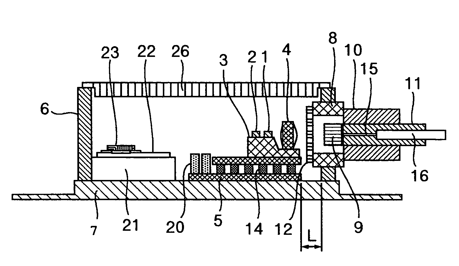
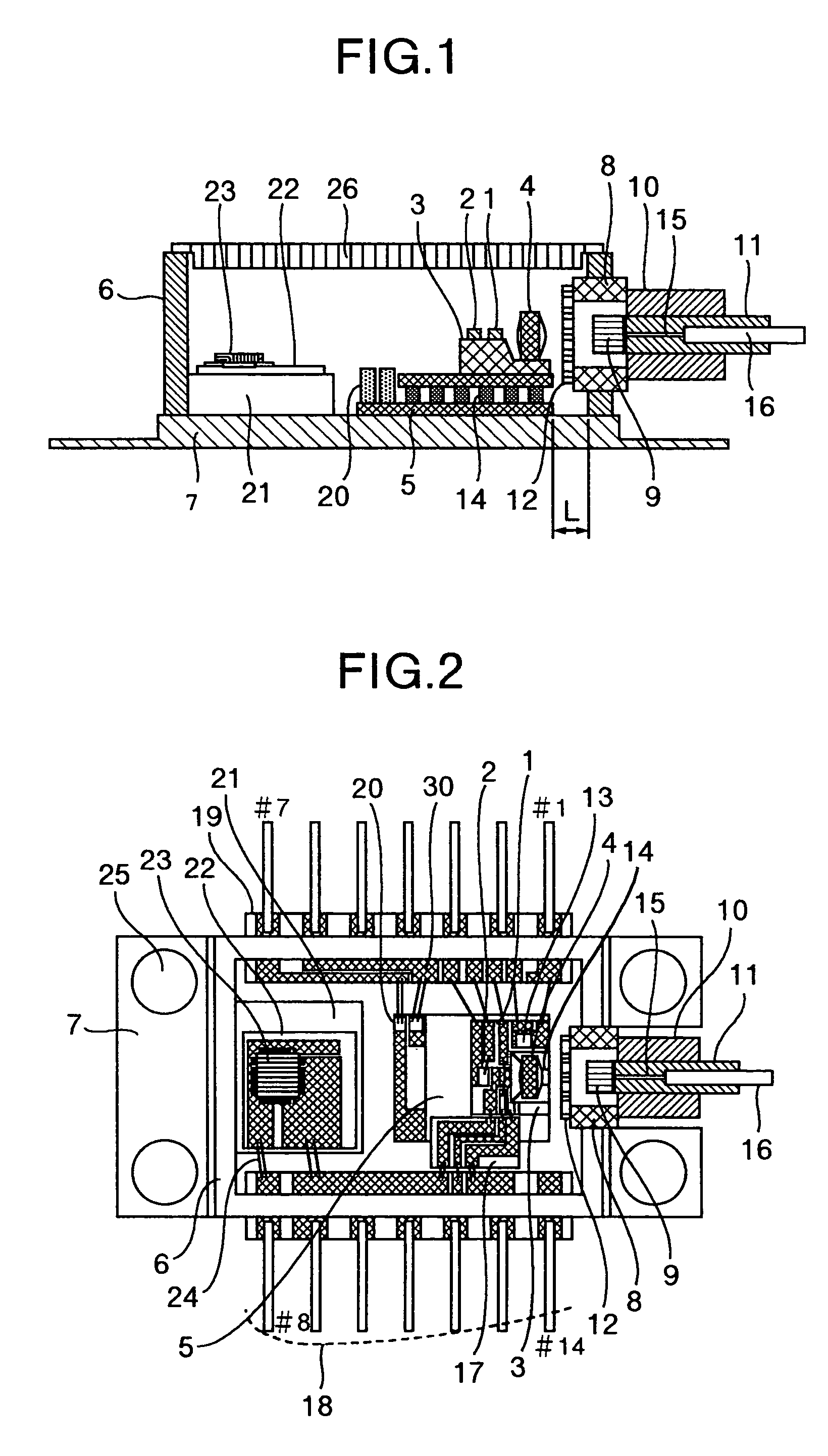
[0032]FIG. 1 is a longitudinal sectional view showing a construction of an optical coupling apparatus according to the invention. FIG. 2 is a partially sectional top view of the optical coupling apparatus shown in FIG. 1.

[0033]Referring to FIGS. 1 and 2, the optical coupling apparatus includes a laser diode 1 as a semiconductor light emitting device, a monitor photo-diode 2 as a semiconductor light receiving device for receiving back outgoing laser beams of the laser diode 1, an aspherical lens 4 for condensing front outgoing laser beams of the laser diode 1, a temperature monitoring thermistor 13 for monitoring a temperature change with driving of the laser diode 1, a substrate 3 for mounting these laser diode 1, photo-diode 2, aspherical lens 4 and thermistor 13, and a temperature controlling Peltier device 5 for mounting the substrate 3, installed on a base 7. A housing for accommodating the substrate 3 and the Peltier device 5 includes a package 6 having an outer frame, a base 7...

second embodiment

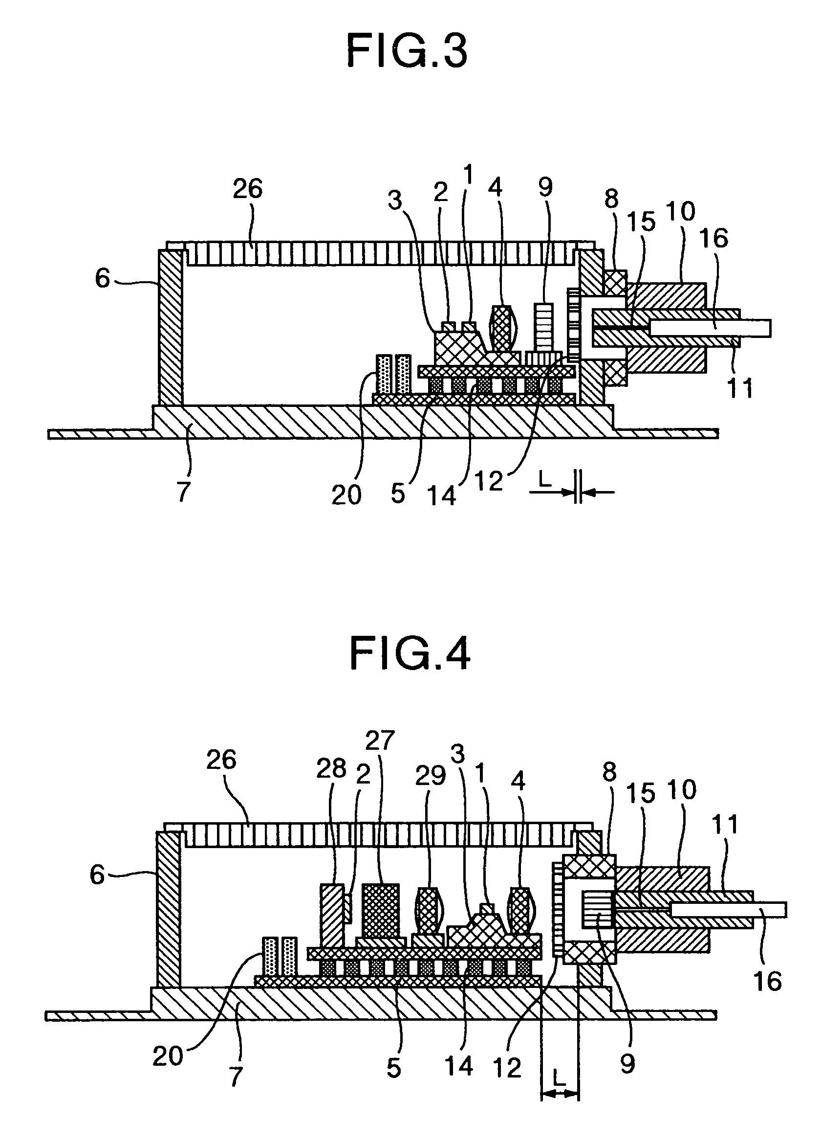
[0052]Next, FIG. 3 is a longitudinal sectional view showing a construction of an optical coupling apparatus according to the invention.

[0053]The embodiment shown in FIG. 3 fundamentally has the same construction as that of the embodiment shown in FIG. 1 with the exception of the following points. In other words, the optical isolator 9 is mounted onto the Peltier device 5 inside the package 6 and the glass window 12 is directly bonded to the package 6.

[0054]The substrate 3 on the Peltier device 5 is arranged at a position away from the optical fiber 15 whereas the optical isolator 9 is mounted at a position close to the optical fiber 15. The optical isolator 9 is of a surface package type such that its lower surface is bonded to the Peltier device 5. The optical isolator 9 is mounted after its position is so adjusted as to introduce the laser beam from the aspherical lens 4. The laser beam is being condensed immediately before and behind the aspherical lens 4 and therefore has a larg...

third embodiment

[0056]Next, FIG. 4 is a longitudinal sectional view showing a construction of an optical coupling apparatus according to the invention.

[0057]The embodiment shown in FIG. 4 fundamentally has the same construction as that of the embodiment shown in FIG. 1 with the exception that a mechanism for monitoring the wavelength of the laser diode 1 is added to the Peltier device 5. A coupling lens 29 for condensing the rear outgoing laser beam of the laser diode 1 is arranged at the back of the laser diode 1 (on the left side of the sheet of drawing in FIG. 4), and the photo-diode 2 receives the laser beam through an optical filter 27. Two photo-diodes 2 are fitted to a carrier 28. One of them receives the laser beam through the optical filter 27 and the other directly receives the condensed beam from the coupling lens 29 without passing through the optical filter 27. The optical filter 27 transmits only the laser beam having a specific wavelength, and the beam reception amount of the photo-d...


PUM


Abstract

An optical coupling apparatus having a temperature control element on which a semiconductor light emitting element, a substrate and a lens are mounted, the semiconductor light emitting element being mounted on the substrate, and rays of light from the semiconductor light emitting element being introduced into the lens. A base on which the temperature control element is disposed, a through-hole portion formed in a housing wall portion installed on the base, penetrating through the housing wall portion and having a wall surface portion longer than a thickness of the housing wall portion and an optical fiber communicated with the through-hole portion and receiving converted light from the lens introduced thereto. A length of the substrate in a direction connecting the light emitting element to the optical fiber is within a range from 0.1 to 0.25 with respect to a length of the base sandwiched by the housing walls of the substrate.

Description

CROSS REFERENCE TO RELATED APPLICATION[0001]This is a continuation of U.S. application Ser. No. 10 / 355,001, filed Jan. 31, 2003, now U.S. Pat. No. 6,821,030, the subject matter of which is incorporated by reference herein.BACKGROUND OF THE INVENTION[0002]This invention relates to an optical coupling apparatus including a semiconductor light emitting device and an optical fiber that are optically connected to each other. More particularly, the invention relates to a single lens optical coupling apparatus that attains optical coupling by use of a single lens.[0003]A known optical coupling apparatus allows an outgoing beam from a semiconductor laser to be incident into an end face of an optical fiber through a lens, and optical coupling is attained between the semiconductor laser and the optical fiber through the single lens, as described in JP-A-05-150146. This reference discloses a construction in which the semiconductor laser, the lens and a light reception device are mounted onto a...

Claims


Application Information

Patent Timeline
Patent Type & Authority Patents(United States)
IPC IPC(8): G02B6/36G02B6/42H01S5/022H01S5/024
CPCG02B6/4201G02B6/4204G02B6/4208G02B6/4243G02B6/4271G02B6/4256
Inventor FUKUDA, KAZUYUKIKUWANO, HIDEYUKINIWA, YOSHIAKIMATSUSHIMA, NAOKI
Owner LUMENTUM JAPAN INC
Learn More