
Pipe joint device and method for manufacturing the same

Active Publication Date: 2018-02-08
JOINTOP
View PDF4 Cites 1 Cited by
  • Summary
  • Abstract
  • Description
  • Claims
  • Application Information

AI Technical Summary

Benefits of technology

The present invention is about a new pipe joint device that can keep various mechanical elements stable without a separate support member and without separately processing its inner surface. This makes it easier and more efficient to manufacture and use the device.

Problems solved by technology

Therefore, a pipe coupling work is troublesome and an assembling process increases, which increase the construction cost.
Also, a usual steel pipe for piping, which is used for the pipe joint device of the related art is thin, so that it is difficult to perform the welding or the screwing at the construction site.
However, according to the former configuration, it is not easy to process the inner peripheral surface of the pipe joint device of which a thickness is not so great.
According to the latter configuration, the separate support element is provided, so that the structure becomes complicated and the cost increases.
However, since it is necessary to form the tapered surface, the groove and the like for supporting the mechanical elements on the inner peripheral surface, a mold of high mechanical precision is required upon the casting, which increases the cost.

Method used


Image

  • Pipe joint device and method for manufacturing the same
  • Pipe joint device and method for manufacturing the same
  • Pipe joint device and method for manufacturing the same

Examples


Embodiment Construction

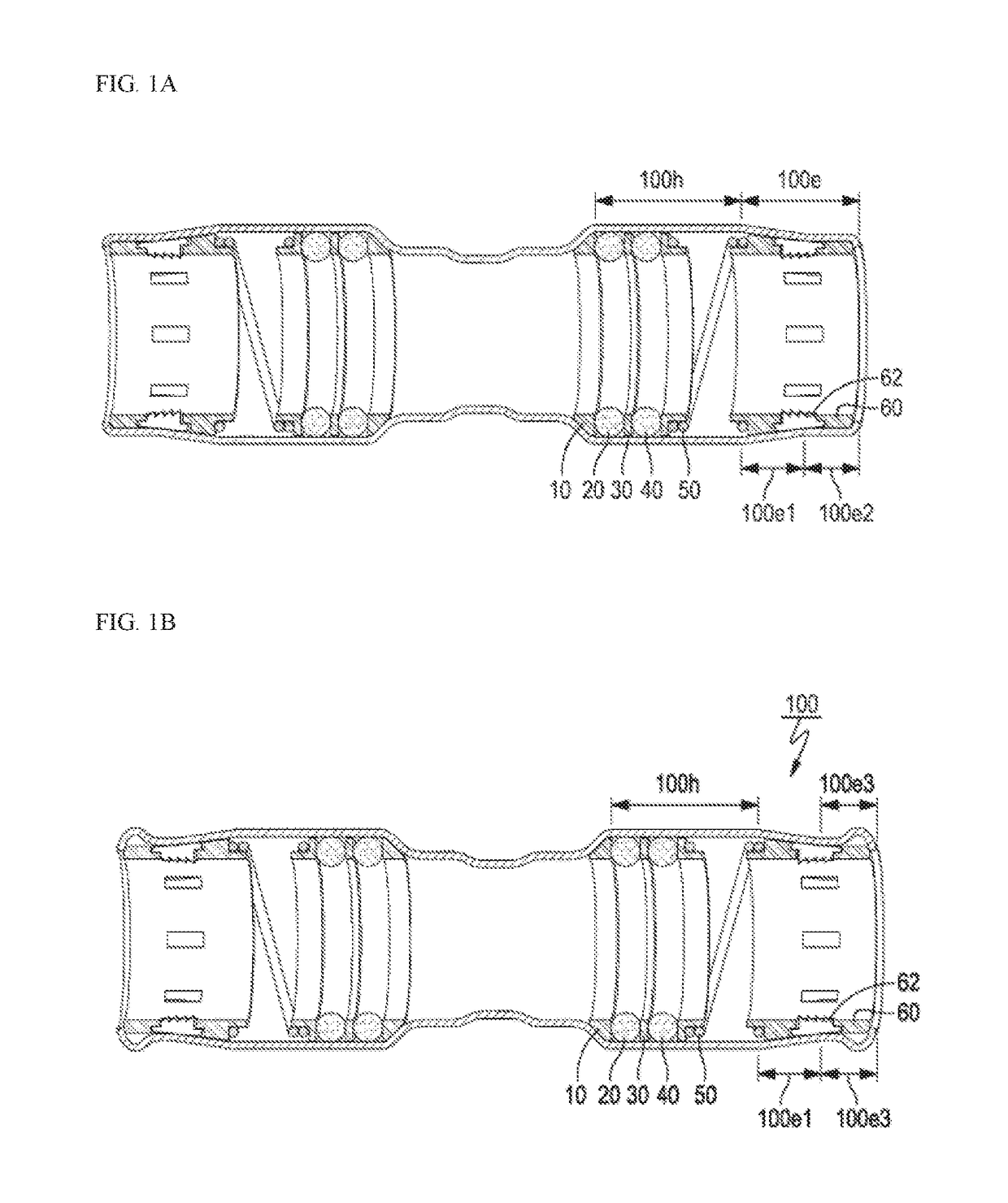
[0025]Hereinafter, illustrative embodiments of the present invention will be described with reference to the accompanying drawings. In the below, descriptions on well-known configurations in the related art, for example, functions and detailed configurations of diverse mechanical elements to be provided in a pipe joint device are omitted. That is, the mechanical elements are to support pipes inserted into the pipe joint device and some of the mechanical elements do not configure a gist of the present invention. Although the descriptions are omitted, one skilled in the art can easily understand the characteristic configurations of the present invention with reference to the following descriptions.

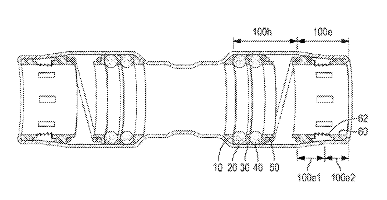
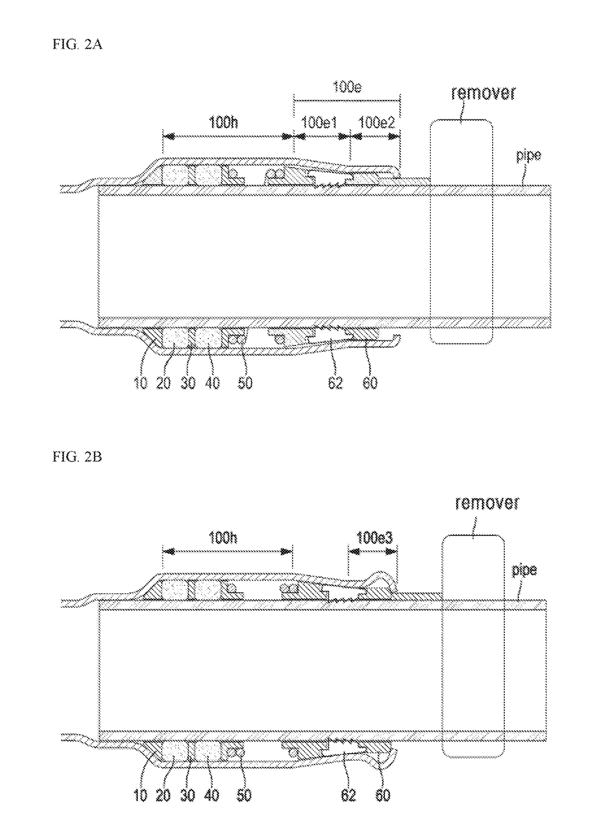
[0026]First, referring to FIGS. 1A and 1B, which are sectional views depicting a structure of a pipe joint device in accordance with an illustrative embodiment of the present invention, FIG. 1A is a sectional view depicting an intermediate-step structure of a final pipe joint device, and FIG...


PUM

PropertyMeasurementUnit
Diameteraaaaaaaaaa
Shapeaaaaaaaaaa

Abstract

A pipe joint device configured to interconnect two pipes to be inserted therein through openings of both opened ends thereof including a joint main body and a joint assembly disposed in the joint main body is provided. The joint main body includes a small-diameter part formed at a central part and large-diameter parts formed at both sides of the small-diameter part. Each of the large-diameter parts has a first horizontal part, a diameter-reduced part of which a diameter gradually decreases from the first horizontal part toward the opening, and a second horizontal part extending horizontally from the diameter-reduced part toward the opening. A portion of each of the second horizontal parts is configured as a curled part inclined toward an outer-diameter direction and the opening of the pipe joint device and then again inclined toward an inner-diameter direction and the opening and having a mountain-shaped section as a whole.

Description

CROSS-REFERENCE TO RELATED APPLICATION[0001]The present application claims priority under 35 U.S.C. 119A to Korean Patent Application No. 10-2016-0098848 Filed on Aug. 3, 2016, which is herein incorporated by reference in its entirety.TECHNICAL FIELD[0002]The present invention relates to a pipe joint device, and more particularly, to a pipe joint device capable of enabling pipings for water supply, heating and cooling and air conditioning, which are used for industry or home, to be easily attached and detached, and having improved an assembling property of a component, and a method for manufacturing the same.RELATED ART[0003]A pipe joint device configured to couple two pipes has been known (for example, refer to a Korean Utility Model Application Publication No. 20-2012-2695A).[0004]In general, a pipe joint device is a mechanical device configured to couple pipings into a variety of forms such as a linear shape, an elbow shape, a T-shape, a cross shape and the like upon establishmen...

Claims


Application Information

Patent Timeline
IPC IPC(8): F16L37/092
CPCF16L37/0925B21D39/048B21D41/02F16L21/02B21D26/051B21D39/04F16L37/0927B21D19/12B21D39/20B21D41/026F16L37/08F16L37/084F16L37/092
Inventor AHN, JAE-MINLEE, GYU-CHANCHO, NAM-HYUNG
Owner JOINTOP
Learn More