
Observation optical system and observation device

a technology of optical system and observation device, which is applied in the field of observation optical system, can solve the problems of many lenses being required for aberration correction, the power ratio between the positive and negative lens units is excessively increased, and the effect of shortening the optical system by making the objective optical system into a telephoto type system is low, and achieves good optical performance and antivibration sensitivity. high

Inactive Publication Date: 2005-07-19
CANON KK
View PDF11 Cites 6 Cited by
  • Summary
  • Abstract
  • Description
  • Claims
  • Application Information

AI Technical Summary

Benefits of technology

[0013]It is an object of the present invention to provide an observation optical system which has an objective optical system having a high antivibration sensitivity while ensuring a space for an image inverting system, antivibration driving mechanism, and the like between the objective optical system and an eyepiece optical system and can obtain good optical performance with a lens arrangement constituted by a small number of lenses.

Problems solved by technology

Since they require a certain space, the merit of shortening the optical system by making the objective optical system into a telephoto type system is low.
However, since the power ratio between the positive and negative lens units excessively increases, many lenses are required for aberration correction.
It is therefore theoretically impossible to increase the antivibration sensitivity.

Method used


Image

  • Observation optical system and observation device
  • Observation optical system and observation device
  • Observation optical system and observation device

Examples


Embodiment Construction

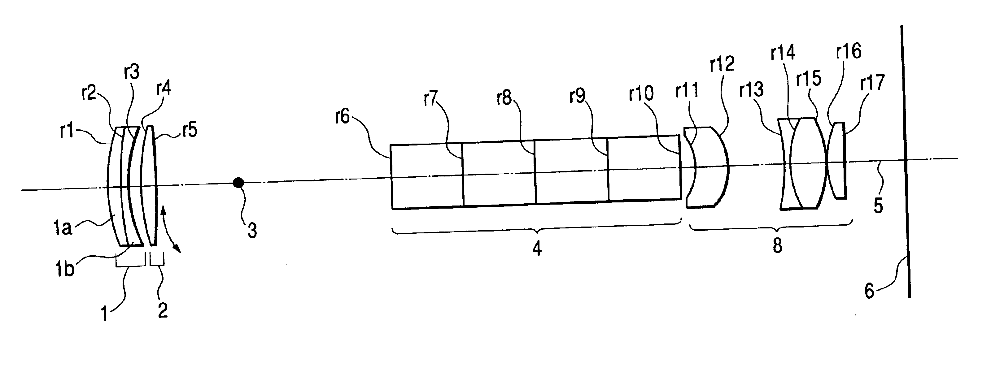
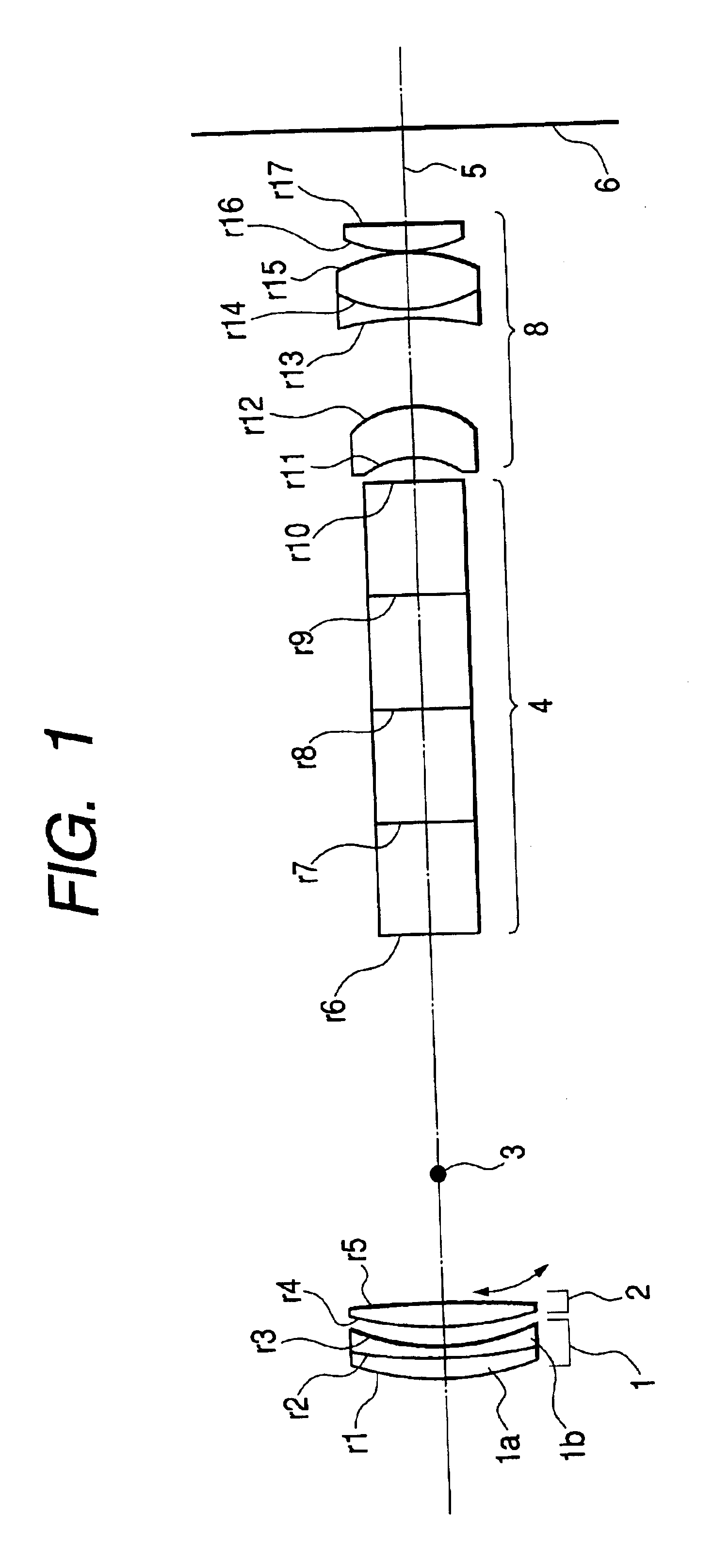
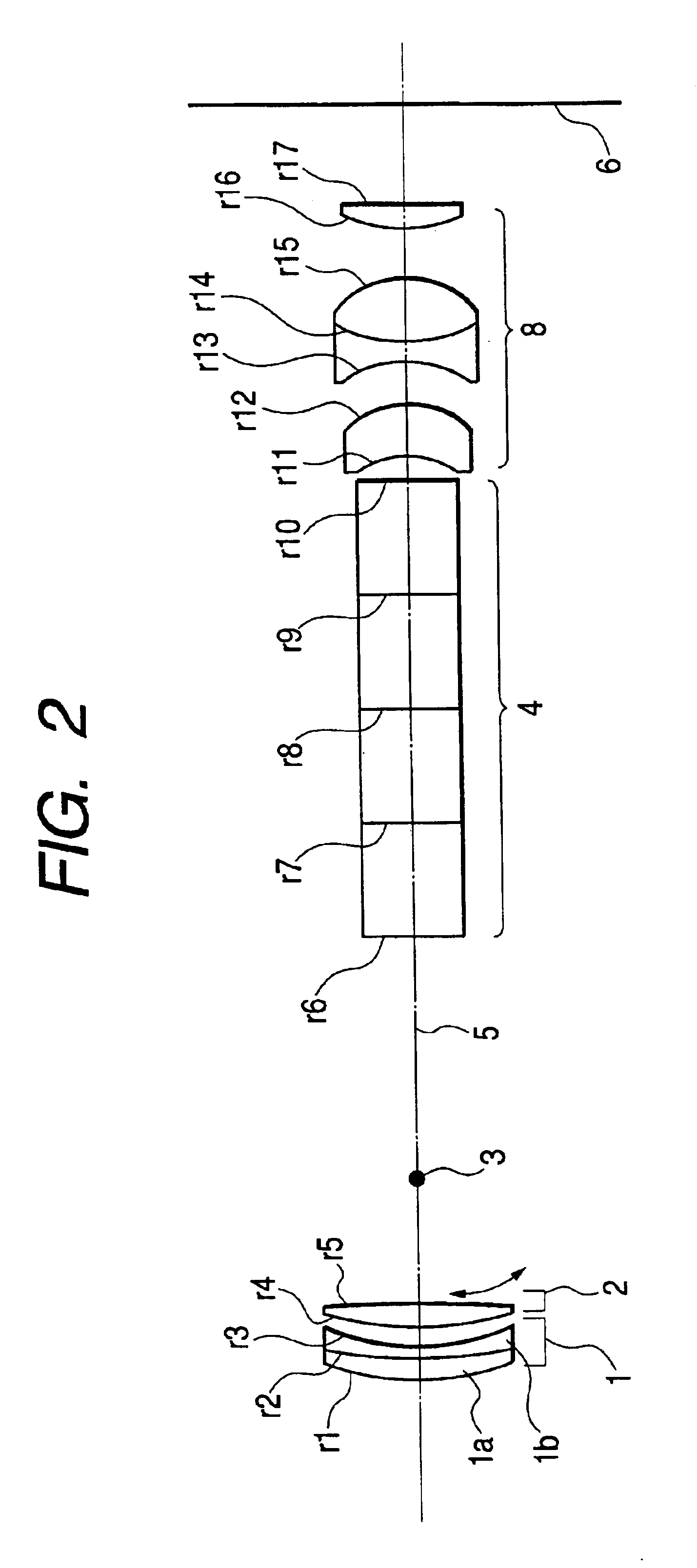
[0027]FIGS. 1 to 6 show the arrangements of observation optical systems based on numerical embodiments 1 to 6 according to an embodiment of the present invention.

[0028]Referring to FIGS. 1 to 6, a first lens unit 1 has a negative power (=reciprocal of focal length), and a second lens unit 2 has a positive power. A point 3 on an optical axis 5 indicated by the chain line in each drawing serves as a swing center when the second lens unit 2 is driven for antivibration.

[0029]Note that an objective lens part is comprised of the first and second lens units 1 and 2. An image-erecting prism 4 is part of an image inverting part and formed by, for example, a Porro prism or Pechan roof prism. An eyepiece part 8 is comprised of a plurality of lenses. An observation optical system is comprised of the objective lens part, image inverting part, and eyepiece part. Reference numeral 6 denotes a pupil plane of an observer.

[0030]In this embodiment, as described above, the objective lens part is compri...


PUM


Abstract

An observation optical system including an objective optical part which forms an image of an object, an image inverting part which converts an image formed by said objective optical part into an erect image, and an eyepiece optical part which guides the erect image converted by said image inverting part to an observer. The objective optical part has a first lens unit with a negative power and a second lens unit with a positive power arranged from an object side in the order named, and said second lens unit is movable in a direction including a component perpendicular to an optical axis to stabilize an image.

Description

BACKGROUND OF THE INVENTION[0001]1. Field of the Invention[0002]The present invention relates to an observation optical system used for an observation device having an antivibration function, such as a telescope or binocular.[0003]2. Related Background Art[0004]As an observation optical system for an observation device such as a telescope or binocular, an observation optical system having an antivibration function is disclosed in, for example, Japanese Patent Application Laid-Open No. 10-186228.[0005]This observation optical system has an objective optical system having a first lens unit with a positive power (the reciprocal of the focal length) and a second lens unit with a negative power arranged from the object side in the order named, and the second lens unit is driven in a direction perpendicular to the optical axis to effect the antivibration function.[0006]The above objective optical system has a so-called telephoto type arrangement, which is characterized in that the total l...

Claims


Application Information

Patent Timeline
Patent Type & Authority Patents(United States)
IPC IPC(8): G02B23/18G02B23/16G02B27/64G02B13/00G02B25/00G02B23/02G03B5/00
CPCG02B13/04G02B23/18G02B27/646G02B5/04
Inventor MOMOKI, KAZUHIKO
Owner CANON KK
Learn More