Fast, variable, and reliable power system controller design
a power system controller and variable technology, applied in the direction of emergency protective circuit arrangements, emergency protection arrangements for limiting excess voltage/current, electric devices, etc., can solve the problem of affecting the operation of the power system. the effect of reducing the burden on the user
- Summary
- Abstract
- Description
- Claims
- Application Information
AI Technical Summary
Benefits of technology
Problems solved by technology
Method used
Image

Examples
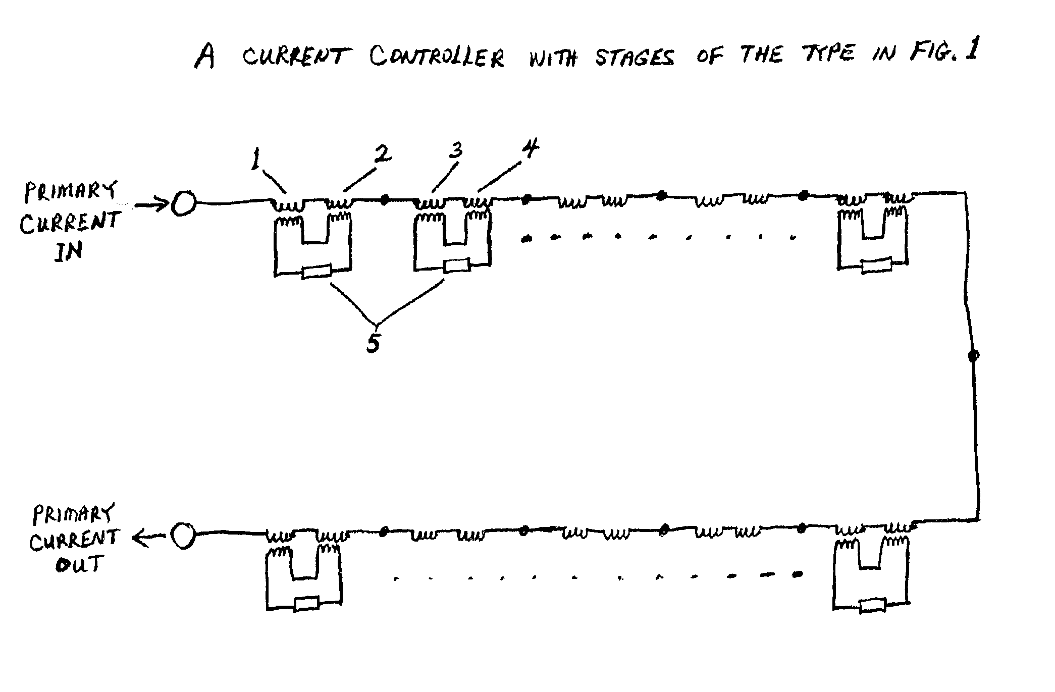
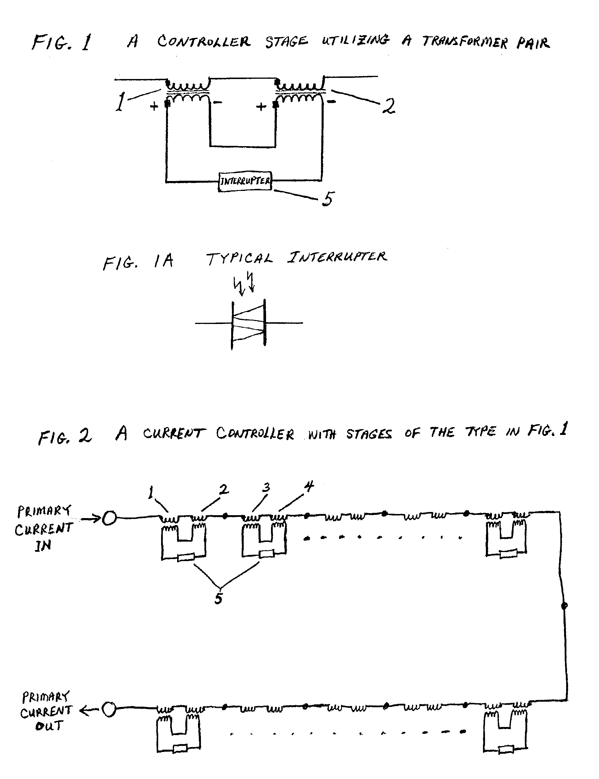
embodiment # 1
Operation—Alternative Embodiment #1
[0039]Since core saturation does not take place in this embodiment we only want to produce a small amount of inductive impedance when individual stages operate. The device would operate almost identically as in the preferred embodiment, except we could introduce slightly more impedance when the first stages operate and for failure of an interrupter, since the cores don't saturate. Also, the operation of consecutive stages in the beginning would add impedance more linearly, again since the cores don't saturate.
Description—Alternative Embodiment #2
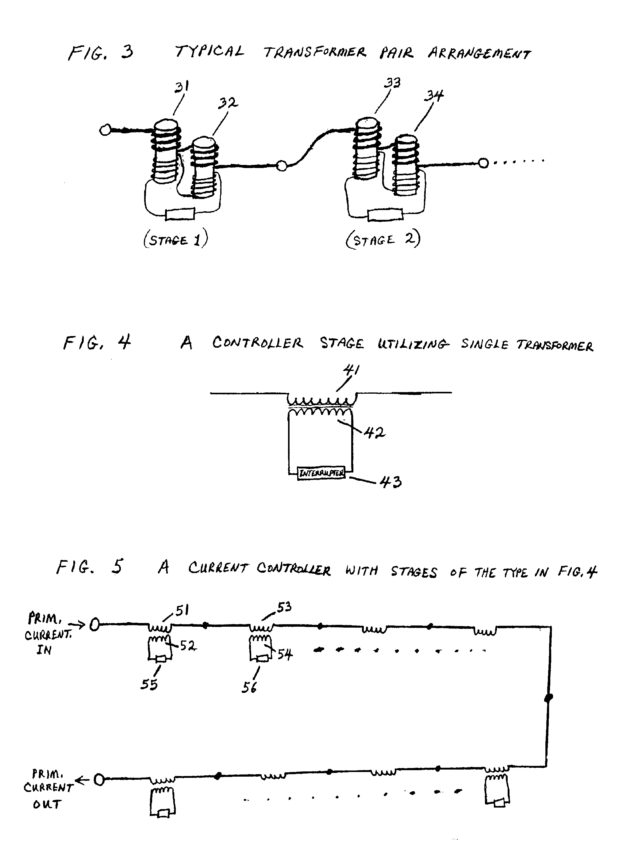
[0040]Another embodiment is illustrated in FIGS. 4, 5, &6. In this embodiment the interrupter (Again, the interrupter can be any device that interrupts or provides resistance or impedance itself) is connected just across the secondary of each transformer, instead of connecting to another transformer with opposite polarity. We just have the interrupter across the secondary of the transformer and the transfor...
embodiment # 2
Operation—Alternative Embodiment #2
[0041]In this embodiment when the interrupters are in the closed or non-resisting mode we provide a dead short across the secondaries of each transformer. This provides no impedance across the primaries and normal current flow is allowed. Upon operation of the interrupters we start to provide inductive impedance across the primary, with the cores saturating on the first ones that operate (or providing little impedance if non-saturating cores are used). Upon operation of several interrupters we then provide significant impedance across the primary. All other aspects would be the same as in the preferred embodiment described earlier, except stages operate as single transformer circuits instead of transformer pairs.
Conclusion, Ramifications, and Scope
[0042]In conclusion the reader can see that the power system controller described in this invention has the unique feature that it takes the energy out of or impedes the primary energy flow in small piece...
PUM
 Abstract
Description
Claims
Application Information
 - R&D Engineer
- R&D Manager
- IP Professional
- Industry Leading Data Capabilities
- Powerful AI technology
- Patent DNA Extraction
Browse by: Latest US Patents, China's latest patents, Technical Efficacy Thesaurus, Application Domain, Technology Topic.
© 2024 PatSnap. All rights reserved.Legal|Privacy policy|Modern Slavery Act Transparency Statement|Sitemap