Method for energy extraction—II

a technology of energy extraction and energy, applied in the direction of lasers, position/direction control, starter details, etc., can solve the problems of quantum electrodynamic theory, continuous creation and destruction of virtual particles, and the theory described above is not the only theory that adequately accounts for its existen

Inactive Publication Date: 2005-07-19
PINTO FAB
View PDF2 Cites 14 Cited by
  • Summary
  • Abstract
  • Description
  • Claims
  • Application Information

AI Technical Summary

Benefits of technology

[0023]An illustrative apparatus for carrying out the inventive method comprises, in one embodiment, a system for accessing zero-point energy (e.g., two Casimir force-generating boundaries) that is operatively coupled to an energy transformation system. In some embodiments, the energy transformation system includes a first device that is operable to alter at least one physical factor of the system, and a second device that is operable to change a distance between the Casimir force-generating boundaries. The first and second devices advantageously operate independently of each other such that, at the same time, the physical factor can be affected and spacing between the boundaries can be controlled.

Problems solved by technology

This non-thermal radiation is believed to result from random fluctuations occurring at the quantum level that result in a continual creation and destruction of virtual particles.
While the Casimir force is “real” in the sense that is observable, the quantum electrodynamic (“QED”) theory described above is not the only theory that adequately accounts for its existence.
Such efforts notwithstanding, investigators have not as yet developed devices and methods that are suitable for commercially exploiting ZPE.

Method used


Image

  • Method for energy extraction—II
  • Method for energy extraction—II
  • Method for energy extraction—II

Examples


Embodiment Construction

[0042]As stated in the Background section, the Casimir force arises (in at least one interpretation) from the imposition of boundary conditions on a source force field, such as the quantum electromagnetic field, the “strong” force field, the gravitational force field, and the “weak” force field. Although the illustrative methods and apparatuses described herein are directed to systems in which the Casimir force arises from interactions with the quantum electromagnetic field, the present invention is also applicable to systems in which the Casimir force arises from interactions with the “strong” force field, the gravitational force field, and the “weak” force field.

[0043]It will be understood that the illustrative embodiments of the present invention do not, literally, “change” or “transform” zero point energy to another form of energy. In particular, in accordance with some embodiments of an illustrative apparatus in accordance with the present invention, Casimir force-generating bo...


PUM


Abstract

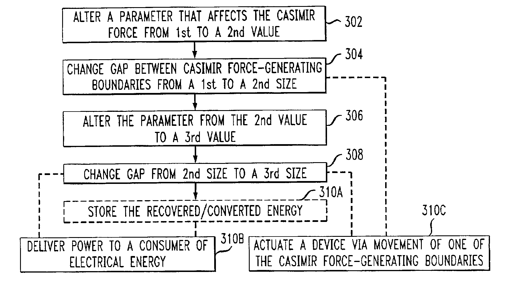
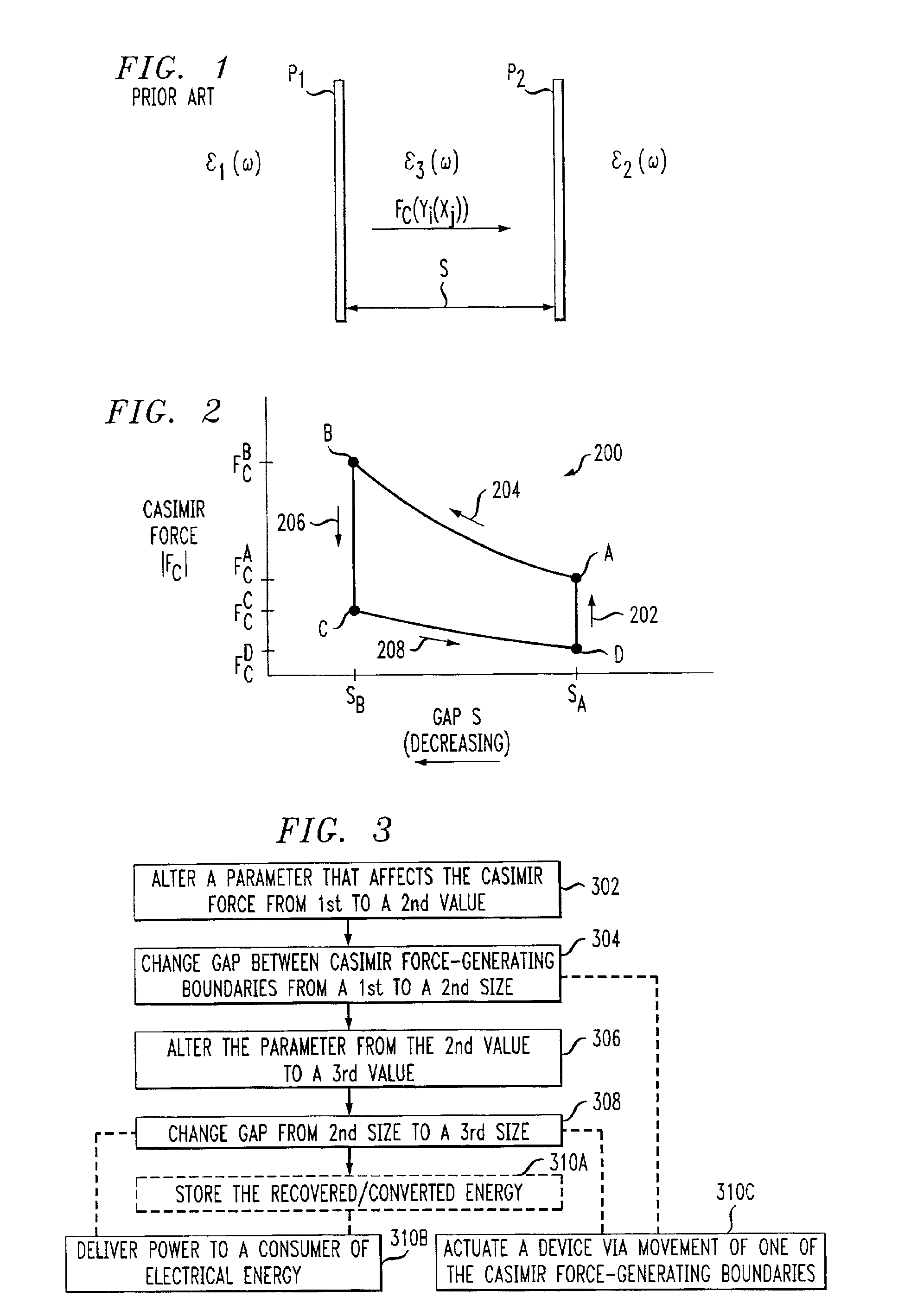
In some embodiments, the illustrative method defines an engine cycle comprising several state changes that allow for a net gain of energy from an underlying source force field. The potential for a net energy gain via the method results from the discovery that a Casimir force system can be rendered non-conservative. This is done by appropriately altering one or more of a variety of physical factors that affect the Casimir force, or by altering any of a variety of environmental factors that affect such physical factors. In various embodiments, the extracted energy is stored, used to power energy-consuming devices or used to actuate a micromechanical device. In one embodiment, the method is implemented using an energy extraction apparatus that comprises two spaced Casimir force-generating boundaries that are operatively coupled to an energy transformation system. The energy transformation system includes a first device that is operable to alter at least one physical factor of the system. The energy transformation system also includes a second device that is operable to change the distance between the two Casimir force-generating boundaries, and further operable to maintain the distance between the boundaries while the first device alters the physical factor.

Description

STATEMENT OF RELATED APPLICATIONS[0001]This application is a division of and claims priority of U.S. Pat. App. No. 09 / 578,638 filed May 25, 2000, now U.S. Pat. No. 6,477,028 which, in turn, claims priority of U.S. Pat. App. No. 60 / 135,868 filed May 25, 1999.FIELD OF THE INVENTION[0002]The present invention relates generally to the extraction of energy from a source force field, such as the quantum electromagnetic field.BACKGROUND OF THE INVENTION[0003]Three hundred years ago, it was believed that if all matter were removed from a region of space, a completely empty volume —a vacuum —results. One hundred years ago, it was known that even if all matter were removed from a region of space, that region is not truly empty because it still would contain thermal radiation. At that time, however, it was incorrectly believed that a vacuum could still be created by removing the thermal radiation, such as by cooling the region of space to absolute zero.[0004]More recently, theory has predicted...

Claims


Application Information

Patent Timeline
Patent Type & Authority Patents(United States)
IPC IPC(8): F03G7/00H02N11/00H02N1/00
CPCF03G7/00H02N1/00H02N11/00H02N11/008
Inventor PINTO, FABRIZIO
Owner PINTO FAB
Why Eureka
Try Eureka