
Belt apparatus used in image formation, and an image formation apparatus

a technology of image formation and belt, applied in the direction of electrographic process apparatus, instruments, optics, etc., can solve the problems of large impact at the time of contact, inconvenient molding of endless belts, and damage to images formed subsequently, so as to reduce the image quality of transferred images

Inactive Publication Date: 2005-07-19
RICOH KK
View PDF29 Cites 12 Cited by
  • Summary
  • Abstract
  • Description
  • Claims
  • Application Information

AI Technical Summary

Benefits of technology

The present invention provides a belt apparatus and an image forming apparatus that can prevent image quality degradation caused by load variations in the rollers. The belt apparatus has a simple structure and does not require special parts, and the image forming apparatus has excellent image quality consistently. The belt apparatus and image forming apparatus described in the patent text have a roller that drives the belt and a processing unit that acts on the roller, resulting in a rotational load variation that affects the roller. The processing units act on the roller to form an toner image, and the belt is extended between the rollers and driven to ensure stable and accurate image formation.

Problems solved by technology

This residual toner contaminates the surface of the belt 10 and causes the images that are formed subsequently to be damaged.
Moreover, because a hard resin material is used due to its properties when scraping away the residual toner, the impact at the time of contact is large.
With a tandem type belt, an extremely long circumference needs to be secured, however, the molding of the endless belt is prohibitively expensive.
In some cases this position is at substantially the central area between the support rollers, however, in the majority of typical apparatuses, the position where the photosensor is located is not given a great deal of consideration and it is generally fit into any space leftover as a result of the structural layout of the apparatus.
However, if no consideration is given to the location of the photosensor because precedence is being given to the layout, there is a risk that the accuracy of the detection will be deleteriously affected.
If the photosensor is placed at a position away from the support roller, then vibration when the belt is being driven and slackness increase the further the belt is located away from the belt support rollers.
Moreover, in the technology disclosed in JP-A No. 9-54476, the outer peripheral surface of the belt support rollers is used, however, an extremely high degree of accuracy is required in the positioning of the photosensor and the roller when performing detection at the curvature position and if there is even a slight amount of mispositioning, the fear exists that the detection accuracy and stability will be reduced.
Alternatively, the fear arises that the transfer will be poor because of the narrow transfer width.

Method used


Image

  • Belt apparatus used in image formation, and an image formation apparatus
  • Belt apparatus used in image formation, and an image formation apparatus
  • Belt apparatus used in image formation, and an image formation apparatus

Examples


Embodiment Construction

[0079]Preferred embodiments of the belt apparatus used for image formation and the image forming apparatus according to the present invention will now be described. Intermediate transfer type image forming apparatus:

(1) Belt Apparatus for Image Formation

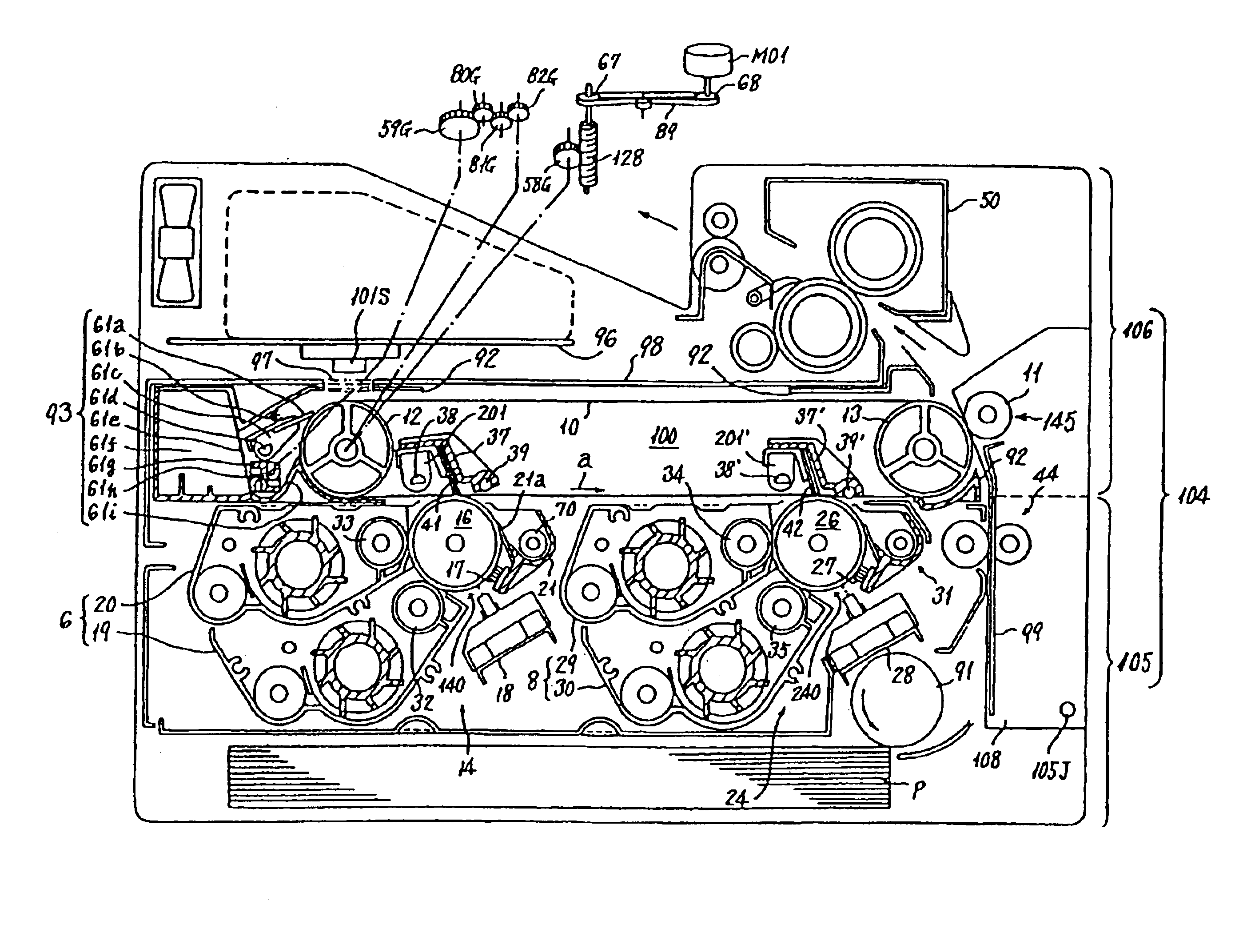
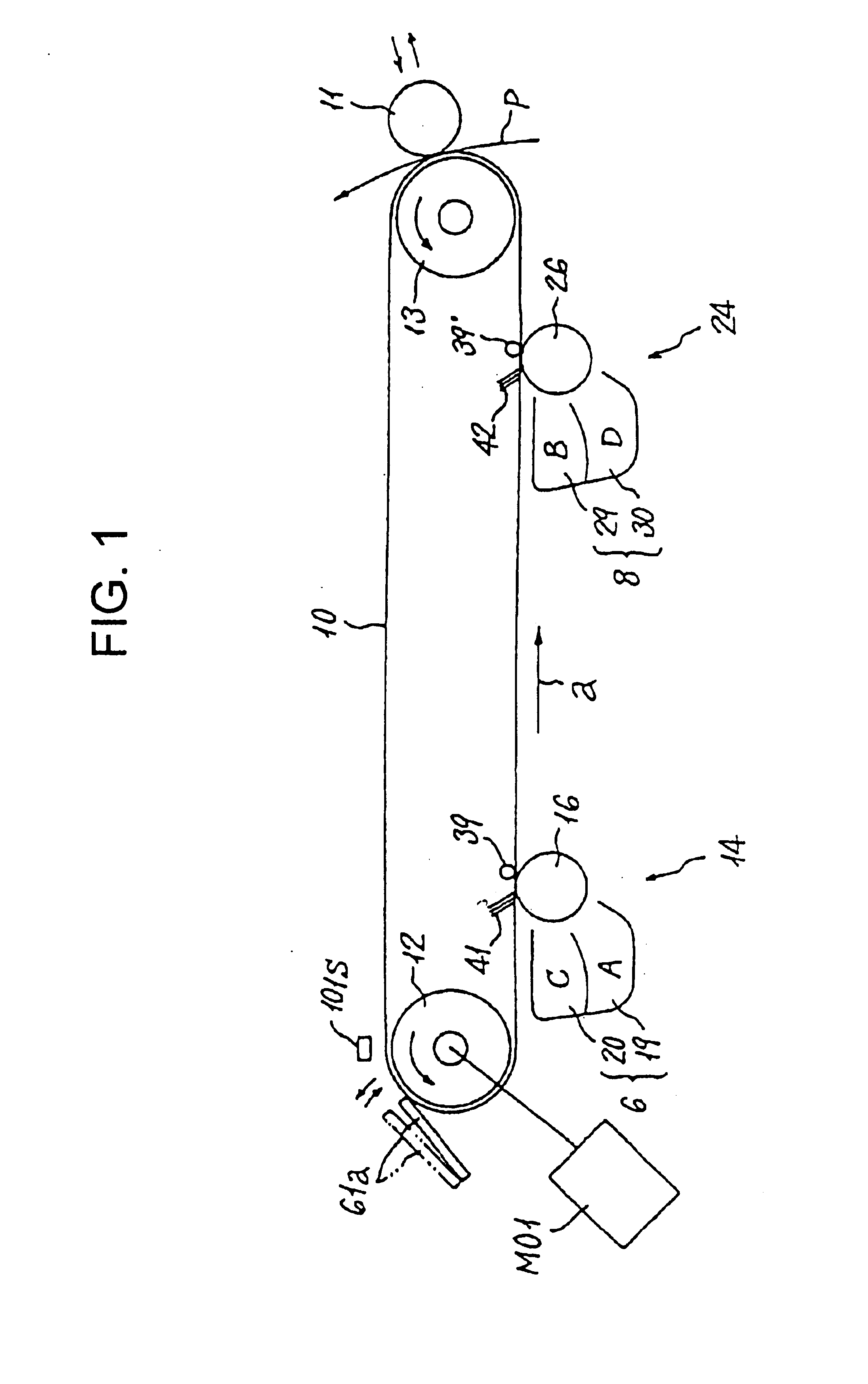
[0080]FIG. 1 shows an example of a belt apparatus used for image formation and an image formation processing unit. Note that the same structural elements as in the belt apparatus used for image formation shown in FIG. 17A, which was described as an example of conventional technology, are provided with the same legends.

[0081]The belt 10 is extended between two rollers 12 and 13 provided at a distance from and facing each other. The belt 10 is rotated by these two rollers 12 and 13.

[0082]The first image forming unit 14, the second image forming unit 24, the transfer roller 11, the cleaning blade 61a, the transfer brushes 41 and 42, and the like are provided as processing unit which forms an image around the belt 10. Other elements are ...


PUM


Abstract

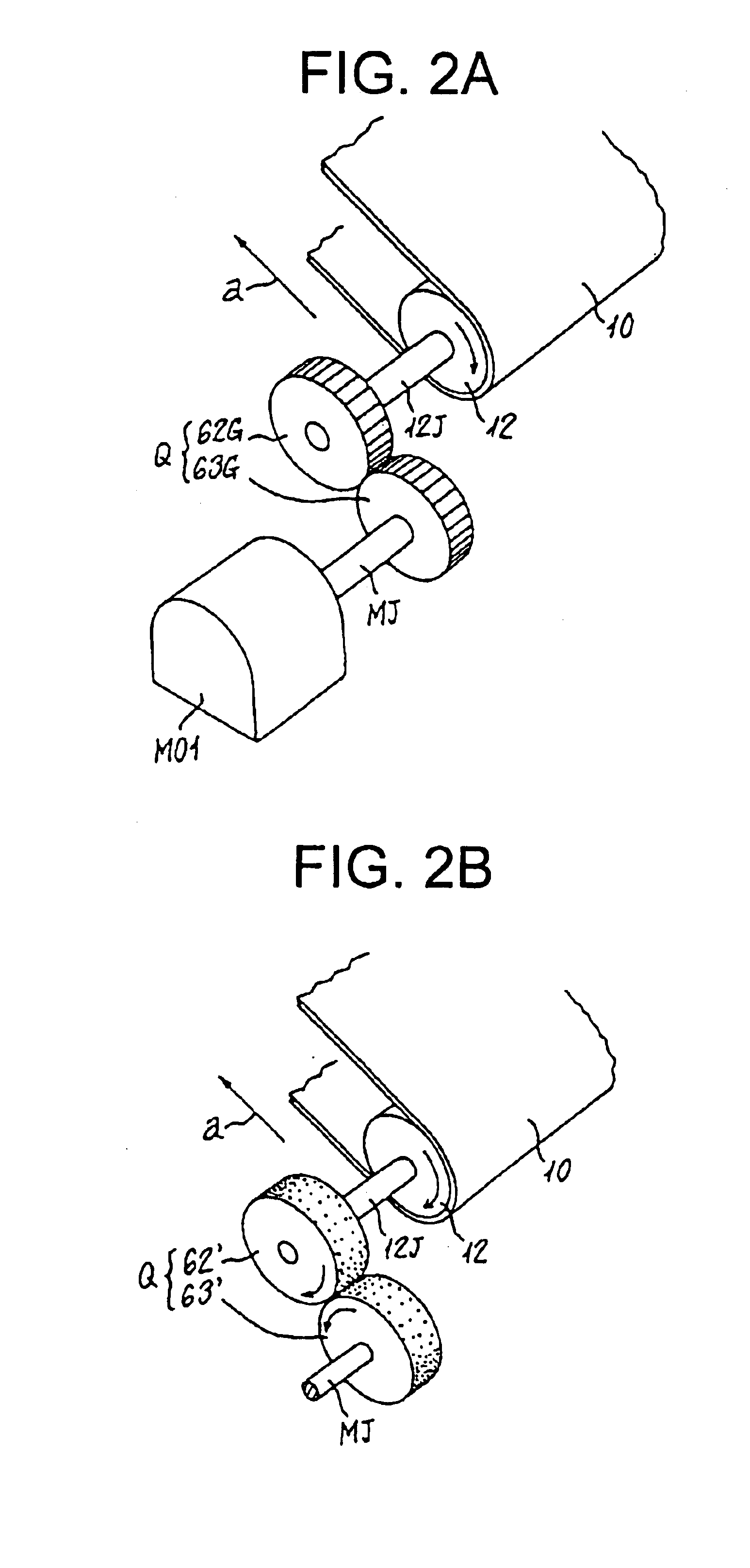
In a belt apparatus used for image formation structured such that processing unit used for image formation are placed around a belt extended between at least two rollers and at least one of the processing unit acts on a roller so as to impart a rotational load thereto, it is possible to avoid a reduction in the image quality of a transfer image on the belt caused by the roller that supports the belt receiving variations in the load due to the movement towards or away from the belt of a cleaning blade. A drive source is connected to the roller to which directly receiving the load variation making this roller the drive roller for the belt.

Description

FIELD OF THE INVENTION[0001]The present invention relates to a belt apparatus used in image formation and to an image forming apparatus.BACKGROUND OF THE INVENTION[0002]Two types of image forming apparatus that use endless belts are used as an image forming unit. One of these apparatuses uses the belt as an intermediate transfer medium, and a plurality of image forming unit are placed around the belt and color toner images are transferred on top of each other directly onto the belt so as to form color toner images having either a plurality or a multiplicity of colors. Thereafter, the color toner images are transferred to a sheet shaped medium such as a paper. Thus this apparatus is known as an intermediate transfer type of color image forming apparatus.[0003]The other apparatus uses the belt as a means for transporting the paper. This apparatus also has a plurality of image forming units placed around the belt, however, the paper is transferred together with the belt and a color ima...

Claims


Application Information

Patent Timeline
Patent Type & Authority Patents(United States)
IPC IPC(8): G03G15/01G03G15/16G03G15/00G03G15/08
CPCG03G15/0131G03G15/161G03G15/1615G03G15/0184G03G15/0121G03G2215/0106G03G2215/0119G03G2215/0154G03G2215/0158
Inventor SAITOH, MASANORIYANAGAWA, NOBUYUKI
Owner RICOH KK
Learn More