Eureka AIR delivers breakthrough ideas for toughest innovation challenges, trusted by R&D personnel around the world.

Trajectory storage apparatus and method for surgical navigation systems

a surgical navigation system and trajectories technology, applied in the direction of radiation beam directing means, catheters, applications, etc., can solve the problems of increasing the radiation exposure of patients and operating room personnel, difficult to visualize the anatomy of patients in three dimensions, etc., and achieve the effect of saving additional trajectories

Inactive Publication Date: 2005-07-19
MEDTRONIC NAVIGATION
View PDF481 Cites 515 Cited by
  • Summary
  • Abstract
  • Description
  • Claims
  • Application Information

AI Technical Summary

Benefits of technology

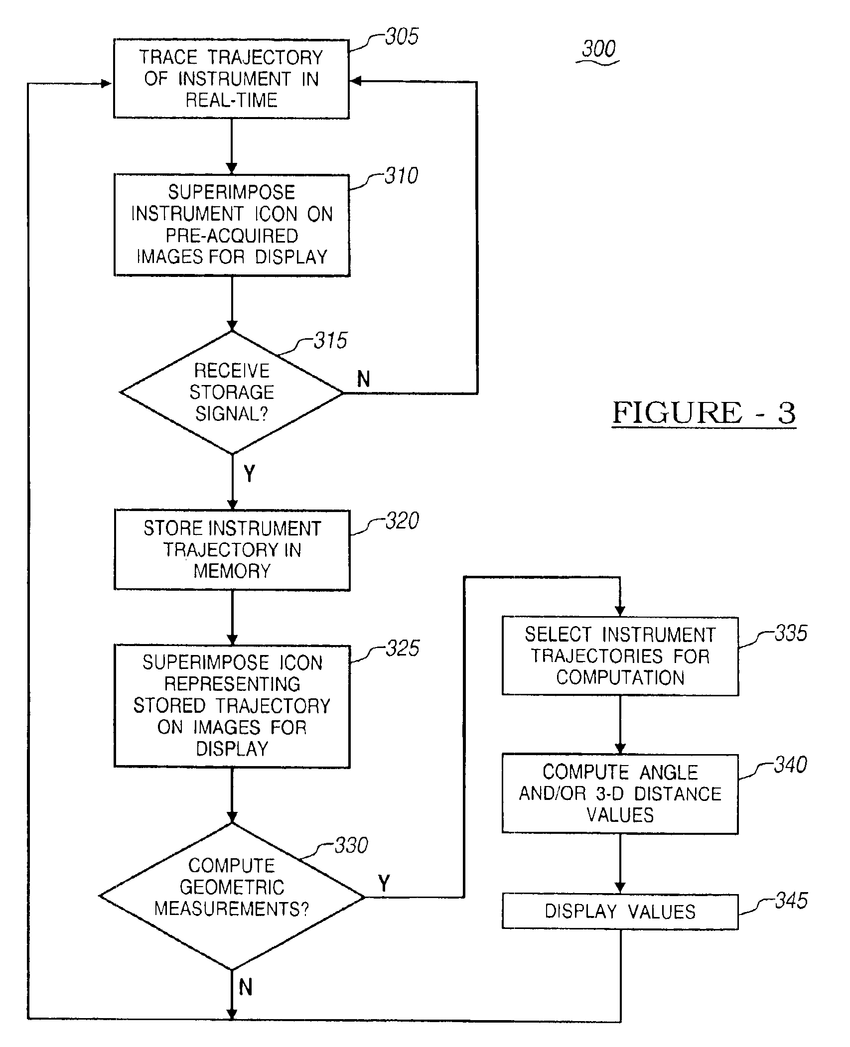
[0010]In one aspect of the invention, an instrument trajectory is tracked in real-time by a surgical navigation system. An icon representing this real-time trajectory is overlaid on one or more pre-acquired images of the patient. At the surgeon's command, the navigation system can store the trajectory of the instrument and, if desired, create a static icon representing the saved trajectory for display on each pre-acquired image. The icon representing the stored trajectory is simultaneously displayed with the real-time trajectory's icon so the surgeon may visually compare them. The surgeon has the option of saving additional trajectories by reissuing the storage command.
[0011]In another aspect of the invention, the surgeon may measure angles between pairs of any two trajectories. The angles are computed in the plane of the image, and are, therefore, computed separately for each image displayed. One option is to compute one or more angles between the real-time trajectory and saved trajectories. These angles are preferably computed and displayed on each pre-...

Problems solved by technology

These procedures are typically used when the visualization of a surgical tool could be obscured by a patient's anatomy, or when the surgical tool is visible but the patient's anatomy may be difficult to visualize in three dimensions.
This can be a time consuming process which increases the amount of radiation exposure to the patient and operating room personnel.

Method used


Image

  • Trajectory storage apparatus and method for surgical navigation systems
  • Trajectory storage apparatus and method for surgical navigation systems
  • Trajectory storage apparatus and method for surgical navigation systems

Examples


Embodiment Construction

[0023]Reference will now be made in detail to the present preferred embodiments of the invention, examples of which are illustrated in the accompanying drawings. Wherever possible, the same reference numbers will be used throughout the drawings to refer to the same or like parts.

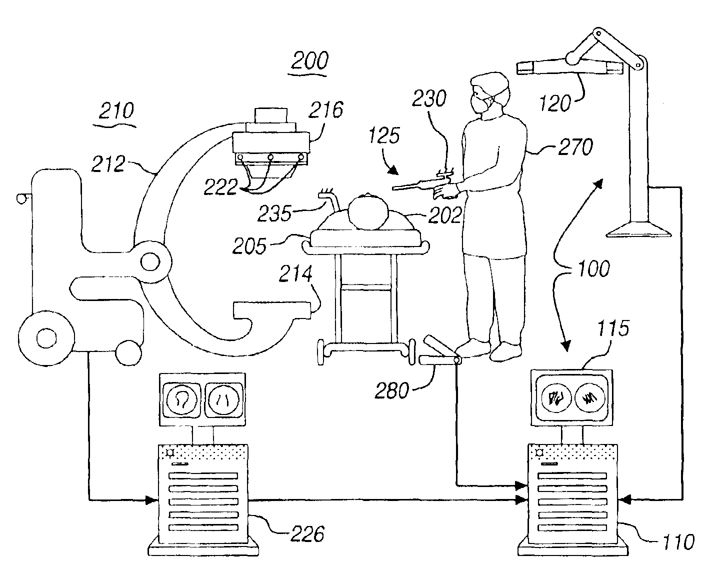
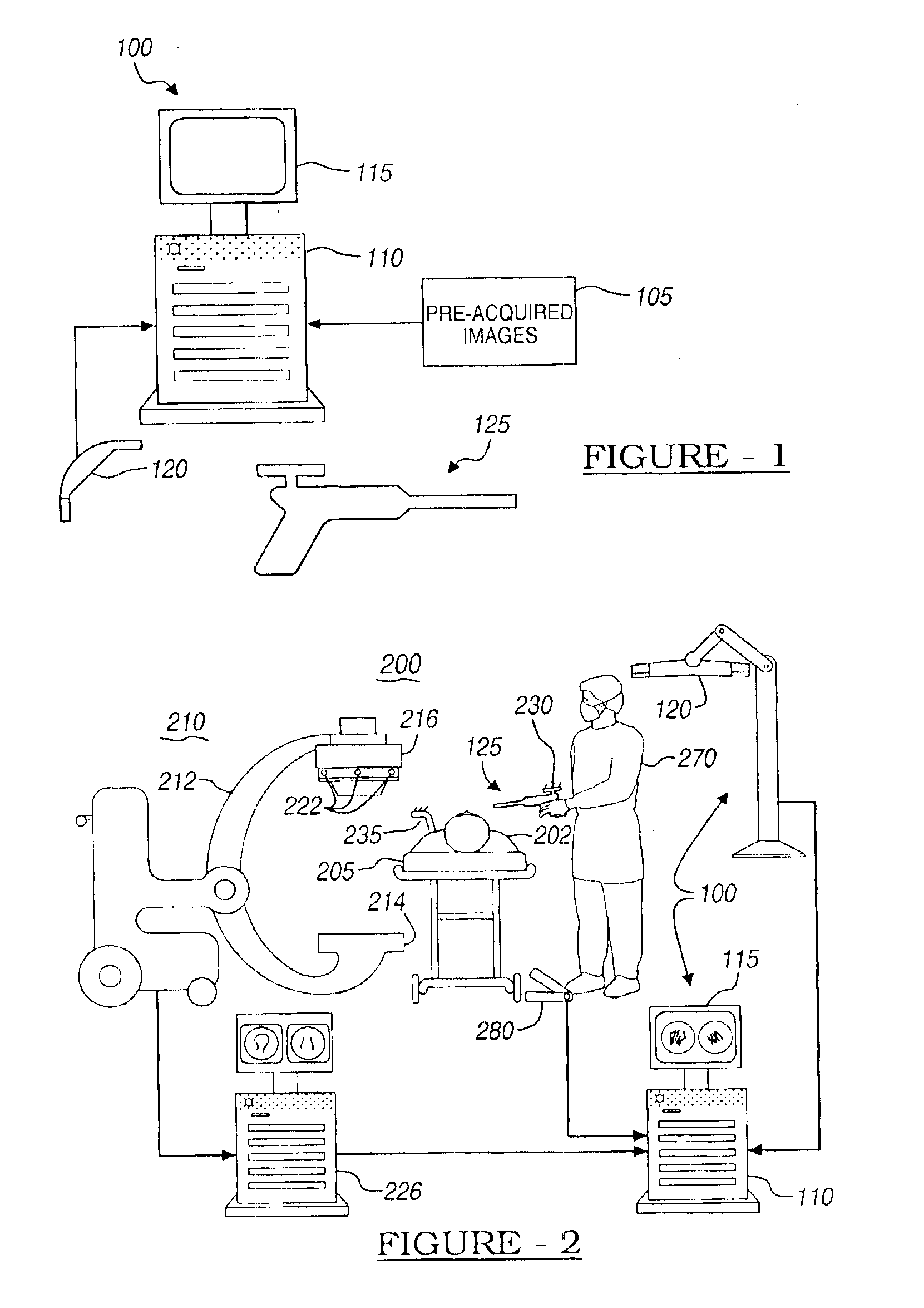
[0024]With reference to FIG. 1, there is shown schematically an apparatus in accordance with the present invention for the storage of instrument trajectories. Image-based surgical navigation system 100 enables a surgeon to generate and display on monitor 115 the trajectory of instrument 125, which is preferably a surgical instrument configured in any known manner. Data representing one or more pre-acquired images 105 is fed to navigation computer 110. Navigation computer 110 tracks the position of instrument 125 in real-time utilizing detector 120. Computer 110 then registers and displays the trajectory of instrument 125 with images 105 in real-time. An icon representing the trajectory of instrument 125 is s...


PUM


Abstract

Apparatus and methods are disclosed for use within an image-guided surgical navigation system for the storage and measurement of trajectories for surgical instruments. An icon representing the real-time trajectory of a tracked instrument is overlaid on one or more pre-acquired images of the patient. At the surgeon's command, the navigation system can store multiple trajectories of the instrument and create a static icon representing each saved trajectory for display. The surgeon may also measure a planar angle between any two trajectories. The angle is computed in the plane of the image, and therefore will be computed separately for each image displayed. Furthermore, the surgeon has the option of computing and displaying the three-dimensional distance between two points defined by any two trajectories.

Description

[0001]This application is a continuation of application Ser. No. 09 / 545,092 filed Apr. 7, 2000, which became U.S. Pat. No. 6,535,756 on Mar. 18, 2003.BACKGROUND OF THE INVENTION[0002]1. Field of Invention[0003]The present invention is directed generally to image-guided medical procedures, and more particularly, to systems and methods for the storage and geometric measurement of instrument trajectories used in image-based surgical guided navigation systems.[0004]2. Description of the Related Art[0005]Image based surgical techniques have been used with success in aiding physicians for performing a wide variety of delicate surgical procedures. These procedures are typically used when the visualization of a surgical tool could be obscured by a patient's anatomy, or when the surgical tool is visible but the patient's anatomy may be difficult to visualize in three dimensions. Such procedures include, for example, spinal implant placement, the alignment of broken bone fragments, and the fi...

Claims


Application Information

Patent Timeline
IPC IPC(8): A61B19/00A61B5/05A61B6/00A61B6/12
CPCA61B6/12A61B19/52A61B19/5244A61B19/50A61B6/4441A61B19/56A61B2017/00725A61B2019/461A61B2019/504A61B2019/507A61B2019/5238A61B2019/5272A61B2019/5276A61B2034/104A61B90/36A61B2034/2072A61B34/20A61B34/25A61B2090/376A61B2090/061A61B34/10A61B2034/107A61B2090/378
Inventor SIMON, DAVID ANTHONYFOLEY, KEVIN T.CARLS, THOMAS ANDREWMELKENT, ANTHONY J.
Owner MEDTRONIC NAVIGATION
Why Eureka
Eureka Blog
Learn More