Elongated truss boom structures for space applications

a technology of elongated truss and boom, which is applied in the direction of web handling, transportation and packaging, and cosmonautic vehicles. it can solve the problems of limited presently available truss boom maximum length of about sixty meters, and the truss boom is almost impossible to transport in that configuration

Inactive Publication Date: 2005-07-26
THE UNITED STATES OF AMERICA AS REPRESENTED BY THE SECRETARY OF THE NAVY
View PDF49 Cites 47 Cited by
  • Summary
  • Abstract
  • Description
  • Claims
  • Application Information

AI Technical Summary

Problems solved by technology

A pervasive problem with conventional truss booms is that the length of their deployed or elongated configuration makes the truss boom almost impossible to transport in that configuration.
However, for space-borne equipment this solution is not appropriate.
Present space missions require longer truss booms, however, the maximum length of presently available truss booms is limited to about sixty meters.
The limitations of the maximum length of truss booms include their required stowage area and their weight, both attributable in part to the requirement for a storage canister.
As coilable truss booms are helically wound inside of a storage cannister for stowage and transport, coilable truss booms generally utilize thin longerons of low modulus material resulting in low boom stiffness and a long undesirably flexible deployed truss boom.
As articulated truss booms are transported as segments of a manageable length for stowage and transport, deployment of the truss boom requires the segments to be connected together at connection joints, and slippage at these connection joints is a drawback which this type of boom may experience.
As shown in FIG. 1, another major limitation with conventional stowable truss booms 10 is that there is no room within the storage canister 20 for apparatus such as instrumentation or control devices.

Method used


Image

  • Elongated truss boom structures for space applications
  • Elongated truss boom structures for space applications
  • Elongated truss boom structures for space applications

Examples


Embodiment Construction

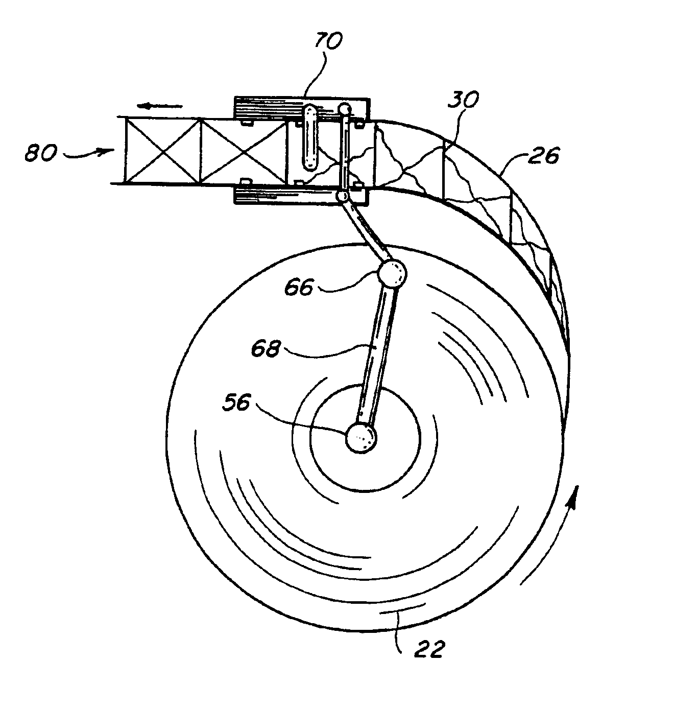
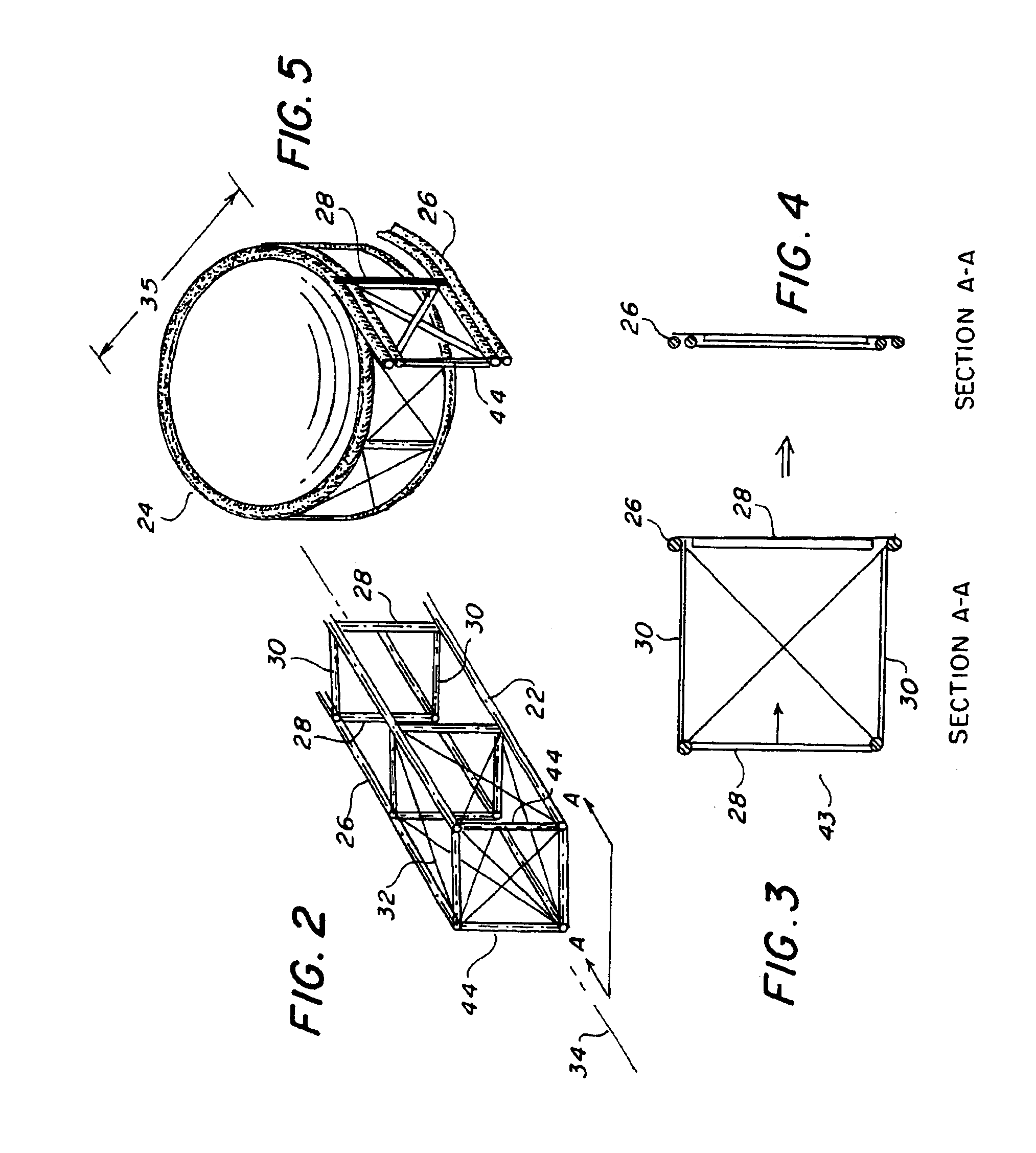
[0045]The present invention provides a truss boom 22 which may be compactly stowed and deployed in space. As shown in FIG. 2, the truss boom 22 includes longerons 26, fixed battens 28, moveable battens 30, and diagonals 32. As shown in FIG. 5, the truss boom 22 is flattened and rolled onto a coil 24 for storage.

[0046]The longerons 26 run along the longitudinal axis 34 of the truss boom 22 as shown in FIG. 2. The longerons 26 are preferably constructed of a material which is structurally stiff, lightweight, and which is capable of being flexed into the large coil 24. In accordance with a preferred embodiment of the invention, the longerons 26, fixed battens 28 and moveable battons 30 are composed of a composite graphite / epoxy material. However, other materials having the above-described properties may be utilized.

[0047]In the embodiment illustrated in FIG. 2, the longerons 26 are preferably formed in the shape of a solid rod having a rounded cross section. Solid rods have two drawbac...


PUM


Abstract

An elongated truss boom structure is adapted to be flattened and coiled to a stowed configuration. The truss boom includes longerons, battens, and diagonals A fixed ladder shaped structure is formed by a plurality of fixedly coupled battens which interconnect two adjacent longerons. The truss boom is flattened for stowage by arranging all of the longerons coplanar to the plane of the fixed ladder shaped structure. The longerons preferably have a corrugated cross section. For stowage the longeron is heated and compressed into a ribbon shaped cross section, and upon deployment the longeron is heated to restore its corrugated cross section. A mechanical assembly machine includes a drum, a stowed flattened truss boom rolled into a coil around the drum, a device for unrolling the coil, an actuating and locking mechanism, and a control arm which connects the actuating and locking mechanism to the drum.

Description

CROSS REFERENCE TO RELATED APPLICATIONS[0001]This application is a divisional of, and claims the priority of, U.S. patent application Ser. No. 09 / 788,407, filed in the United States on Feb. 21, 2001, the entire disclosure of which is hereby incorporated by reference.FIELD OF THE INVENTION[0002]This invention relates in general to an elongated truss boom structure adapted to be flattened and coiled to a stowed configuration. More specifically, the invention is related to an elongated truss boom structure including longerons, fixed batten, moveable battens and diagonals that enable the construction of large scale spacecraft interferometric systems and antennas on a single vehicle.BACKGROUND OF THE INVENTION[0003]This invention relates generally to truss boom structures, and more specifically, to long lightweight deployable truss boom structures. Many space missions require the use of long lightweight deployable truss booms. Truss booms have been used extensively in spacecraft as masts...

Claims


Application Information

Patent Timeline
Patent Type & Authority Patents(United States)
IPC IPC(8): B64G9/00B64G1/22E04C3/00B64G99/00
CPCB64G1/222B64G9/00E04C3/005B64G99/00
Inventor BROWN, MICHAEL A.BUTKIEWIEZ, CHRISTOPHER J.
Owner THE UNITED STATES OF AMERICA AS REPRESENTED BY THE SECRETARY OF THE NAVY
Why Eureka
Try Eureka