Sewing machine

a sewing machine and needle technology, applied in the field of sewing machines, can solve the problems of increasing the cost of controlling the plurality of electromagnets, requiring relative many individual parts, and relatively large mass, and achieve the effect of high flexibility in control and the highest possible precision

Inactive Publication Date: 2005-07-26
PFAFF INDUSTRIESYSTEME & MASCH GMBH
View PDF6 Cites 9 Cited by
  • Summary
  • Abstract
  • Description
  • Claims
  • Application Information

AI Technical Summary

Benefits of technology

[0005]The invention has as its object the avoidance of the above-mentioned disadvantages and the provision of a sewing machine of the previously mentioned kind which assures a high flexibility in the control of the movement of the needle rod and of the sewing foot, especially in the adjustment of the needle stroke, while maintaining the highest possible precision.

Problems solved by technology

This has not only the disadvantage that relatively many individual parts are required and relatively large masses have to be moved, but also that the movement phases of the needle rod and of the sewing foot within a cycle of operation cannot be practically changed.
Along with the considerable expense for the control of the plurality of electromagners, the solution raises above all the disadvantage that the precision of the end positions of the needle rod stroke required for forming a quality stitching can only be obtained with very slow working speeds.

Method used


Image

  • Sewing machine
  • Sewing machine
  • Sewing machine

Examples


Embodiment Construction

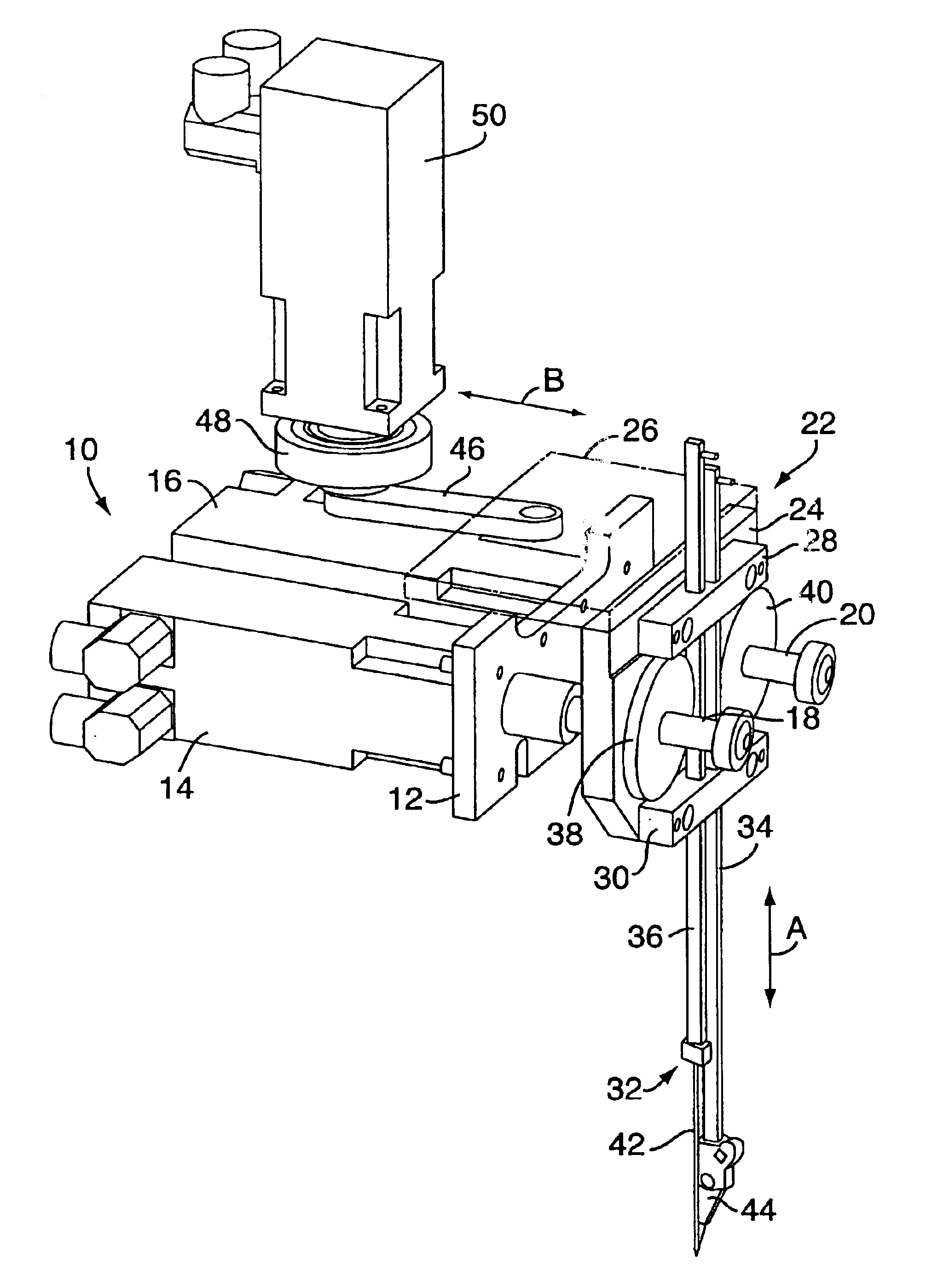
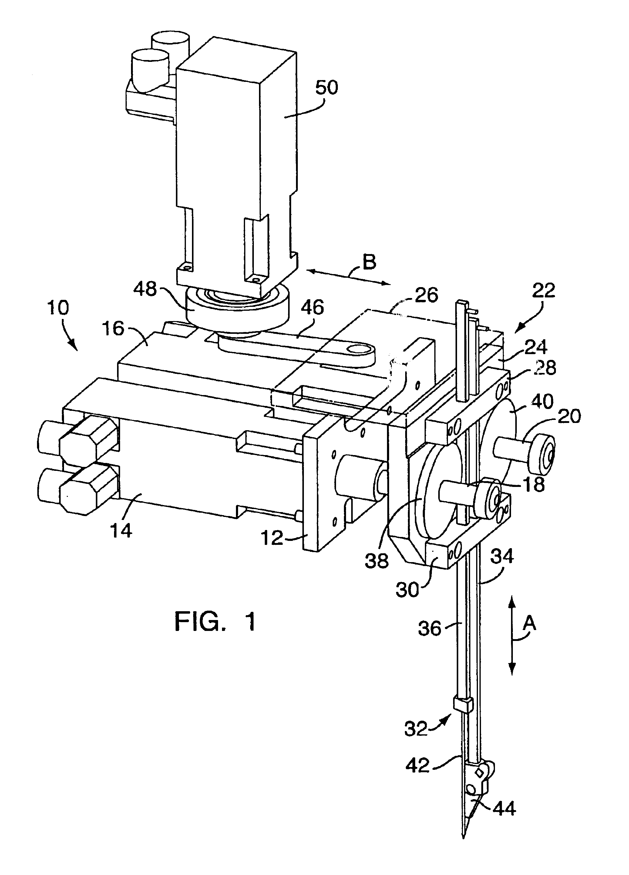
[0015]FIG. 1 shows a sewing machine upper portion, indicated generally at 10, with a plate 12 which is a part of a frame or housing. On the plate 12 and connected to it by flanges are a first and a second servo motor 14 and 16, whose shafts 18 and 20 extend through and outwardly beyond the plate 12.

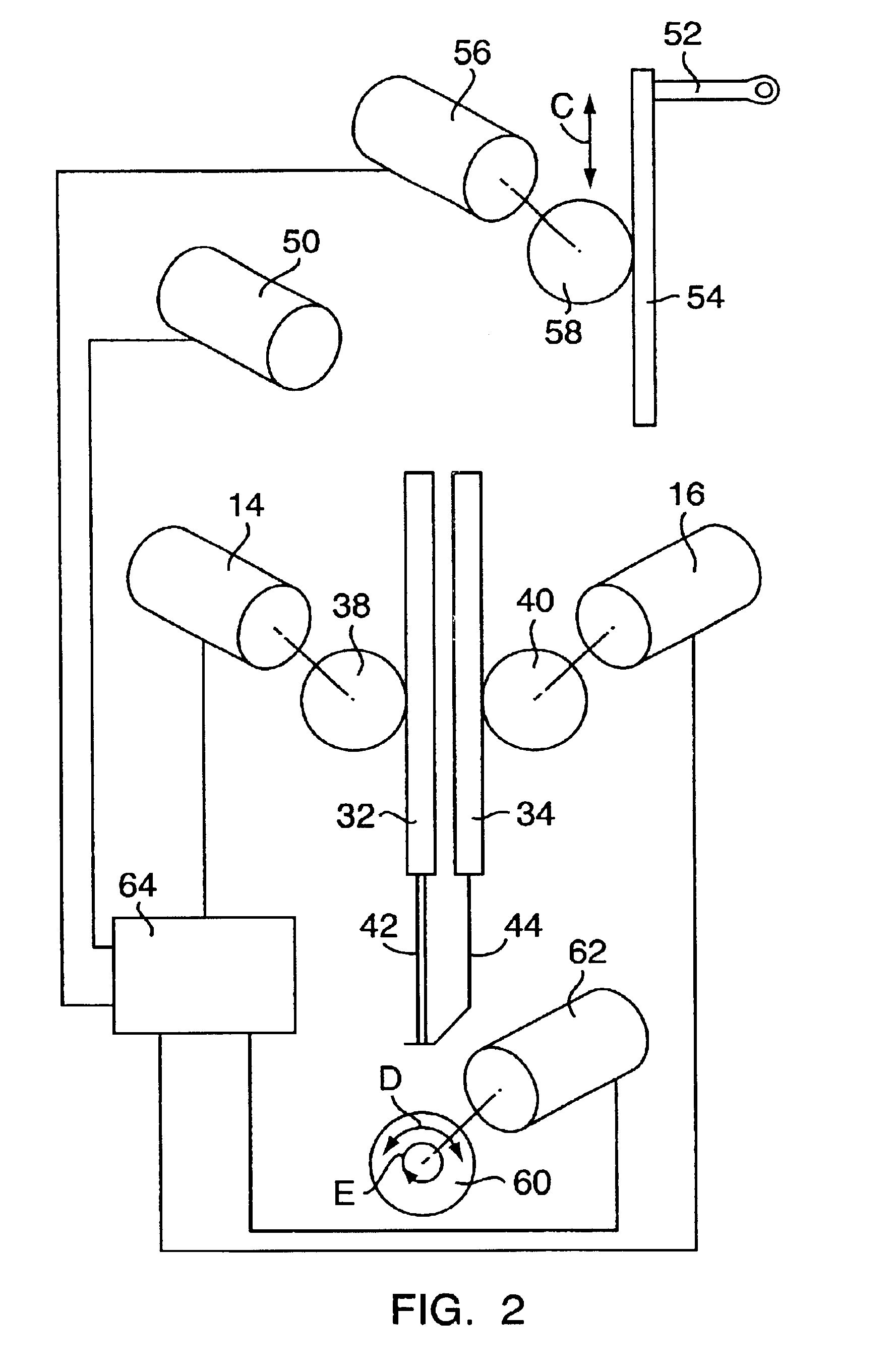
[0016]Mounted on the frame in a non-illustrated way is slide 22 which includes a support plate 24 parallel to the plate 12 and a plate 26, indicated by broken lines only, perpendicular to the support plate 24 and guided for shifting movement in the direction of the double arrow B. On the support plate 24 are guides 28, 30, and a needle rod 32 and a sewing foot or presser foot rod 34, both guided for up and down movement in the direction of the double arrow A. Each of the rods 32 and 34 has a rack strip 36 standing in meshing engagement with a pinion 38, 40 supported on the support plate 24. The pinions 38 and 40 are axially shiftably arranged on the shafts 18 and 20 and are fixed against ...


PUM


Abstract

A sewing machine including a sewing machine upper portion with a frame, a needle rod and a sewing foot rod, which rods are guided in the frame for back and forth movement parallel to one another, a rack connected with each of the rods and which racks are driven by separate pinions driven by separate electric motors. These motors and possibly other motors for positioning other parts of the sewing machine are separately controlled independently of one another by a program controlled control unit so that the movement of needle road and of the sewing foot rod can be independently program controlled during a sewing procedure.

Description

CROSS REFERENCE TO RELATED APPLICATION[0001]Applicant hereby claims foreign priority under 35 U.S.C. § 119 from German Application No. 102 11 528.1 filed Mar. 15, 2002, the disclosure of which is herein incorporated by reference.FIELD OF THE INVENTION[0002]The invention concerns a sewing machine, including a sewing machine upper portion with a frame, a needle rod and a sewing foot rod, which rods are guided for back and forth movement parallel to one another in the housing, and a drive mechanism for the needle rod and the sewing foot.BACKGROUND OF THE INVENTION[0003]In customary sewing machines the needle rod and the sewing foot, as well as the thread pulling lever, if applicable, are driven from a common shaft whose rotary movement in each case is converted by a crank or an eccentric drive into a linear back and forth movement of the needle rod and of the sewing foot. This has not only the disadvantage that relatively many individual parts are required and relatively large masses h...

Claims


Application Information

Patent Timeline
Patent Type & Authority Patents(United States)
IPC IPC(8): D05B29/02D05B69/10D05B29/00D05B69/00D05B55/14D05B55/00D05B73/00D05B73/02
CPCD05B29/02D05B55/14D05B69/10D05B73/02
Inventor KEILMANN, ROBERT
Owner PFAFF INDUSTRIESYSTEME & MASCH GMBH
Why Eureka
Try Eureka