Valve timing adjustment device

a timing adjustment and valve technology, applied in the direction of machines/engines, mechanical equipment, output power, etc., can solve the problems of difficulty in achieving the desired intermediate phase with precision, and achieve the effect of facilitating the formation of guide passages, and increasing the degree of freedom

Inactive Publication Date: 2005-07-26
DENSO CORP +1
View PDF6 Cites 17 Cited by
  • Summary
  • Abstract
  • Description
  • Claims
  • Application Information

AI Technical Summary

Benefits of technology

[0007]A valve timing adjustment device according to the present invention includes a guide rotary body and a movable body. The guide rotary body includes a guide passage containing the movable body. The guide passage includes a gradually decreasing region and a gradually increasing region. The gradually decreasing region includes a gradually decreasing radial dimension relative to a centerline thereof. The gradually increasing region includes a gradually increasing radial dimension relative to a centerline thereof. The gradually decreasing and increasing regions are coaxially aligned with and connected to each other. Therefore, the gradually decreasing region slants in the radial direction relative to an axis of the guide rotary body such that its radial dimension gradually decreases toward the rotational centerline between the center and one end of the guide passage. Furthermore, the gradually increasing region slants relative to the axis of the guide rotary body such that its radial dimension gradually increases between the center and another end of the guide passage. Thus, rotation of the guide rotary body relative to a driving rotary body that is synchronized with a drive shaft causes the movable body to travel in a direction within the guide passage according to a direction of the relative rotation.
[0008]When the movable body moves from one end of the guide passage to the other, it first moves away from the centerline and then toward the centerline. A phase change means changes a rotational phase to one of a delay side and an advance side when the movable body moves away from the rotational centerline. The phase change means changes the rotational phase to the other of the delay side and the advance side when the movable body moves closer to the rotational centerline. Therefore, changing the direction of movement of the movable body relative to the rotational centerline changes the direction of change of the rotational phase. In this manner, according to the invention claimed in claims 1 to 13, the direction of change of the rotational phase can only be switched by moving the movable body from one end of the passage to the other. This is achieved through rotation of the guide rotary body relative to the driving rotary body and occurs even if the rotational direction of the guide rotary body never changes. Therefore, the direction of change of the rotational phase can be switched in a short time.

Problems solved by technology

When located in the middle portion of the passage, the movable operating member tends to shift and, therefore, it is difficult to achieve the desired intermediate phase with precision.

Method used


Image

  • Valve timing adjustment device
  • Valve timing adjustment device
  • Valve timing adjustment device

Examples


first embodiment

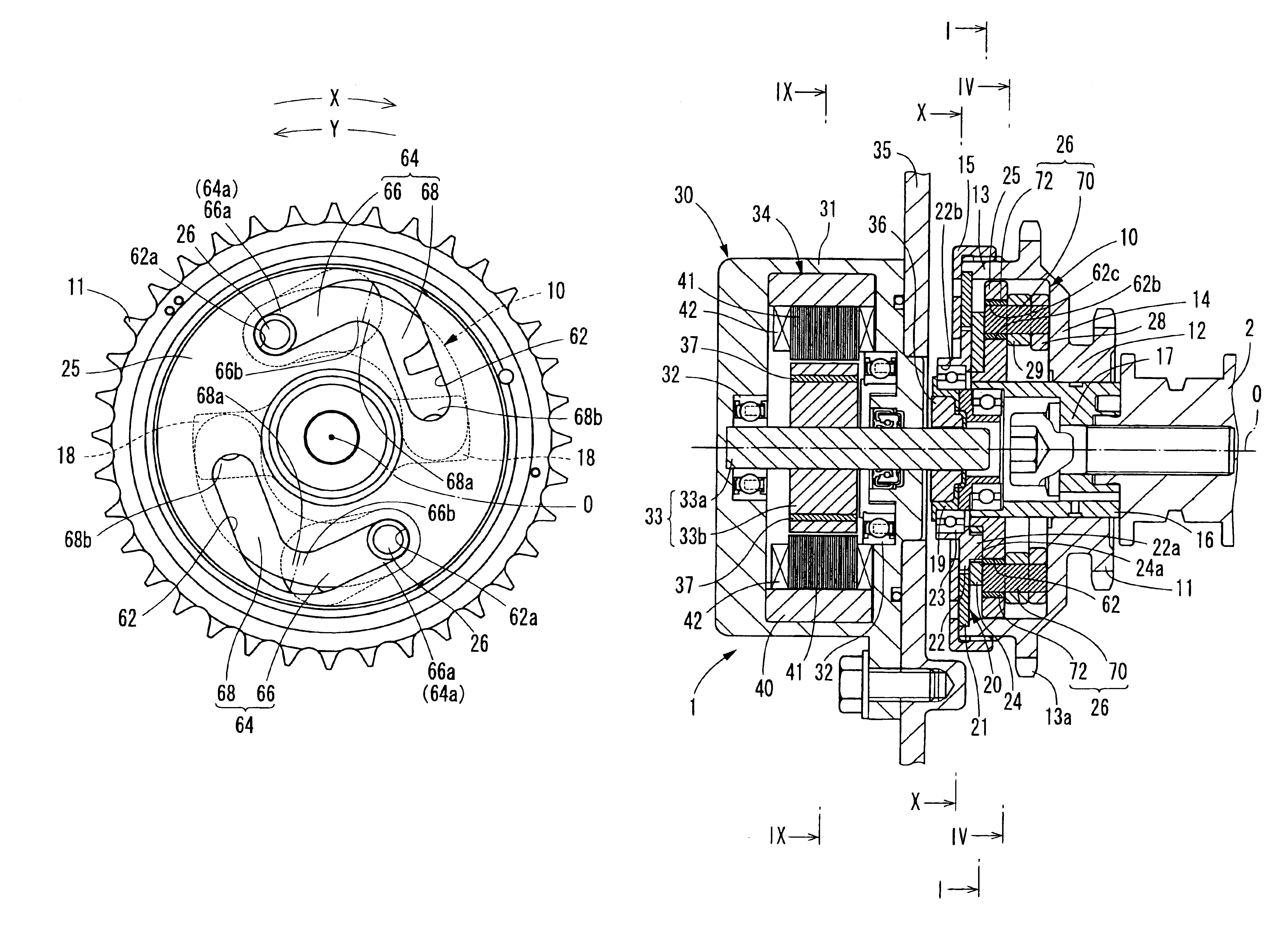
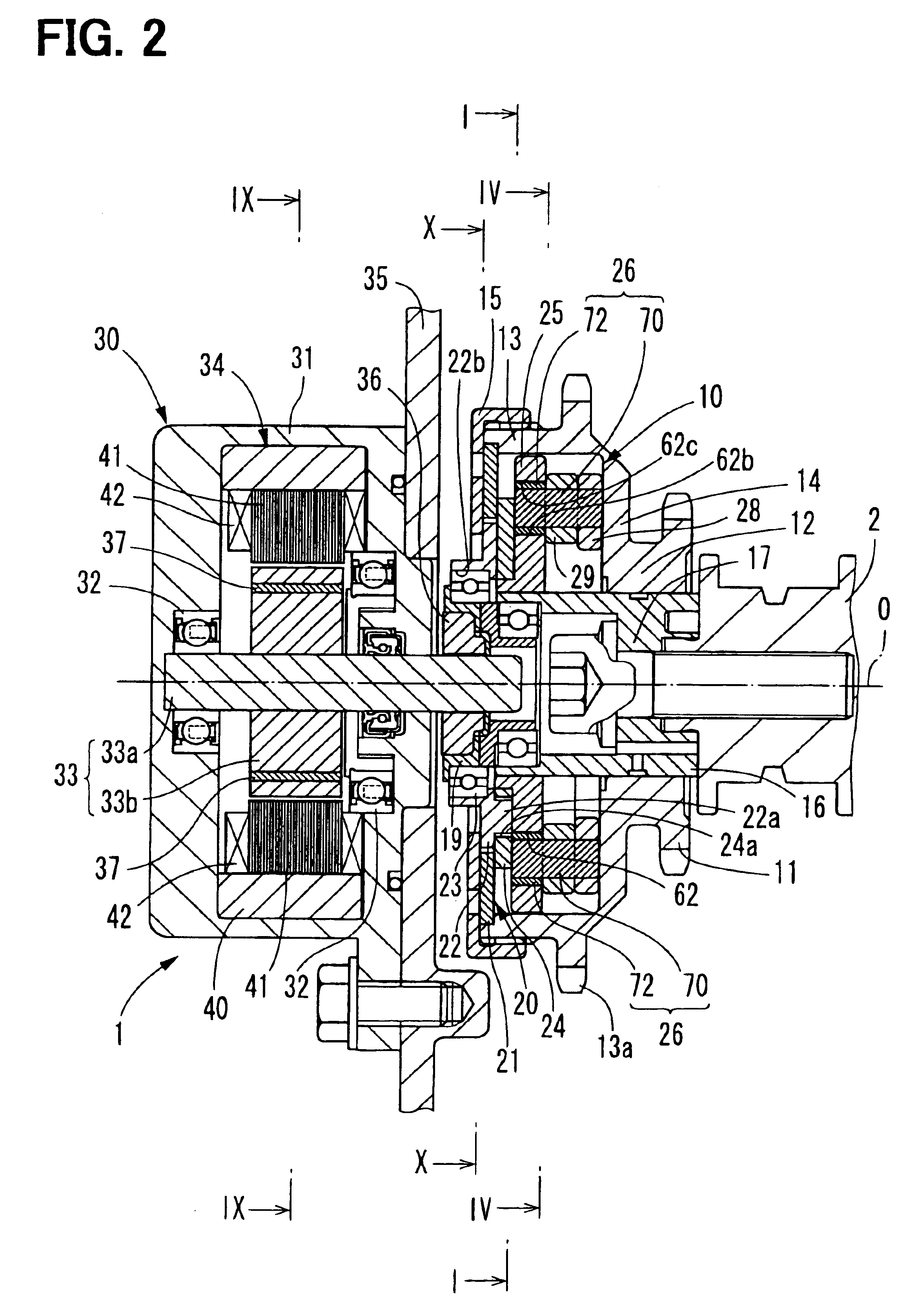
[0040]FIG. 2 depicts a valve timing adjustment device 1 according to the first embodiment of the present invention. The valve timing adjustment device 1 generally includes a transmission system for transmitting a drive torque from a drive shaft such as a crankshaft to a driven shaft such as a camshaft 2 of an engine. The valve timing adjustment device 1 adjusts the valve timing of an intake valve of the engine by changing the rotational phase of the camshaft 2 relative to the crankshaft. A hollow arrow identifies this change in FIG. 3.

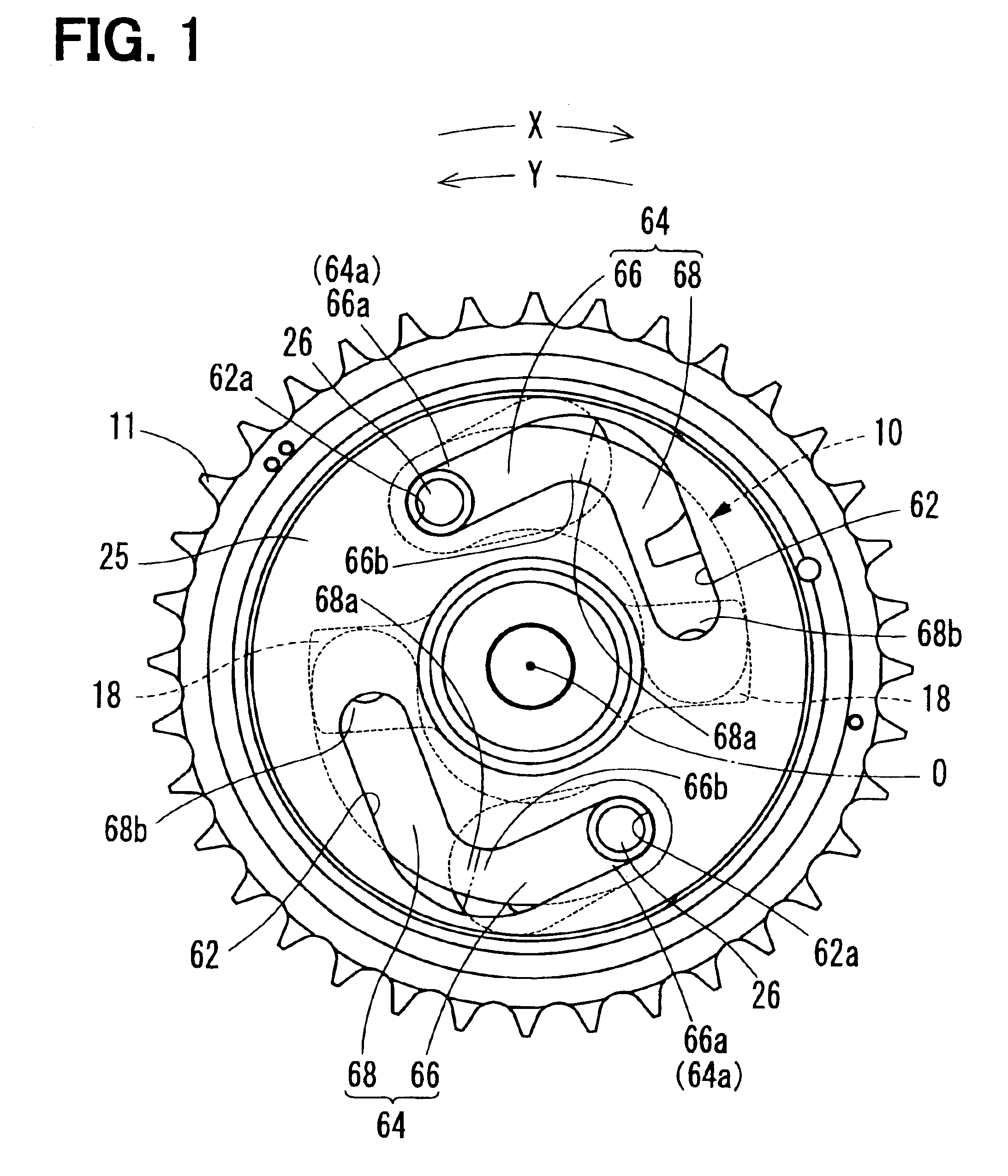
[0041]The valve timing adjustment device 1 includes a phase change mechanism 10, a guide rotary body 25, a movable body 26, an electric motor 30, and a speed reducer 20.

[0042]FIG. 2 and FIG. 4 depict the phase change mechanism 10 including a sprocket 11, an output shaft 16, and arm members 28, 29. As stated above, the phase change mechanism 10 changes the rotational phase of the camshaft 2 relative to the crankshaft. It should be noted that for the sak...

second embodiment

[0081]FIG. 11 depicts a valve timing adjustment device in accordance with the second embodiment of the present invention. The second embodiment of the present invention is a modification of the first embodiment and, therefore, substantially same constituent parts denoted by the same reference symbols.

[0082]In the second embodiment, the gradually decreasing region 66 and the gradually increasing region 68 are formed in a curved shape. Furthermore, the end 66b of the gradually decreasing region 66 and the end 68a of the gradually increasing region 68 are connected to each other in a curved shape. Here, a double dot and dashed line in FIG. 11 shows the connection boundary between the end 66b and the end 68a.

[0083]According to the second embodiment and as shown in FIG. 12, the shaft phase can be changed linearly with respect to the rotational phase of the guide rotary body 25 to the sprocket 11. This provides a constant ratio of speed-reduction between the guide rotary body 25 and the ...

third embodiment

[0084]FIG. 13 depicts a valve timing adjustment device in accordance with a third embodiment of the present invention. The third embodiment of the present invention is a modification of the first embodiment and, therefore, substantially same constituent parts are denoted by the same reference symbols.

[0085]In the third embodiment, the gradually decreasing region 66 is slanted from the end 66b toward the end 66a in the delay direction Y and away from the rotational centerline O. Furthermore, the end 64a of the guide passage 64 blocked by the stopper 62a is common with the end 68b of the gradually increasing region 68. The gradually increasing region 68 is slanted from the end 68a toward the end 68a in the advance direction X and away from the rotational centerline O. Still further, the gradually decreasing region 66 and the gradually increasing region 68 are formed in a curve shape, respectively. Furthermore, the end 66b of the gradually decreasing region 66 and the end 68a of the gr...


PUM


Abstract

A valve timing adjustment device for promptly switching a rotational phase includes a guide rotary body having a guide passage containing a movable body. The guide passage includes a variable radial dimension relative to a rotational centerline. The guide rotary body rotates relative to a driving rotary body and guides the movable body in the guide passage. A phase change mechanism changes the rotational phase of a driven shaft relative to a drive shaft according to the position of the movable body in the guide passage. The guide passage has a gradually decreasing region and a gradually increasing region. The gradually decreasing region slants toward an axis of the guide rotary body. The gradually increasing region slants relative toward the axis of the guide rotary body. The gradually decreasing region and the gradually increasing region are connected.

Description

CROSS REFERENCE TO RELATED APPLICATIONS[0001]This application is based upon and claims the benefit of priority of Japanese Patent Application No. 2003-330142, filed on Sep. 22, 2003, the contents of which are incorporated herein by reference.FIELD OF THE INVENTION[0002]The present invention relates to a valve timing adjustment device for adjusting an opening / closing time (hereinafter referred to as “valve timing”) of at least one of an intake valve and an exhaust valve of an internal combustion engine (hereinafter referred to as an “engine”).BACKGROUND OF THE INVENTION[0003]Power transmission systems such as engines are typically used to transmit drive torque from a drive shaft to a driven shaft. A variety of such engines typically include a valve timing adjustment device. A conventional valve timing adjustment device adjusts the valve timing of the engine by opening or closing at least one of an intake valve and an exhaust valve to change the rotational phase of the driven shaft re...

Claims


Application Information

Patent Timeline
Patent Type & Authority Patents(United States)
IPC IPC(8): F01L1/344F01L1/34F01L1/352F02D13/02
CPCF01L1/022F01L1/352Y10T74/2102F01L2800/00F02D2013/0292F01L2201/00
Inventor TAKENAKA, AKIHIKOINOHARA, TAKAYUKI
Owner DENSO CORP
Why Eureka
Try Eureka