Section mill for wells

Active Publication Date: 2005-07-26
MECOL OIL TOOLS
View PDF3 Cites 85 Cited by
  • Summary
  • Abstract
  • Description
  • Claims
  • Application Information

AI Technical Summary

Benefits of technology

[0009]It is one of the main objects of the present invention to provide a tool for extending its performance o

Problems solved by technology

This obviates the time consuming task of taking out the section mill ass

Method used


Image

  • Section mill for wells
  • Section mill for wells
  • Section mill for wells

Examples


Embodiment Construction

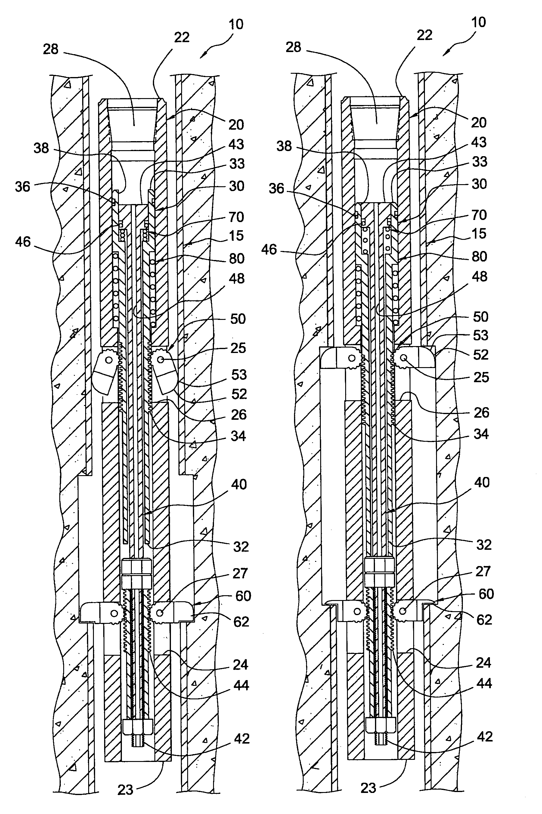
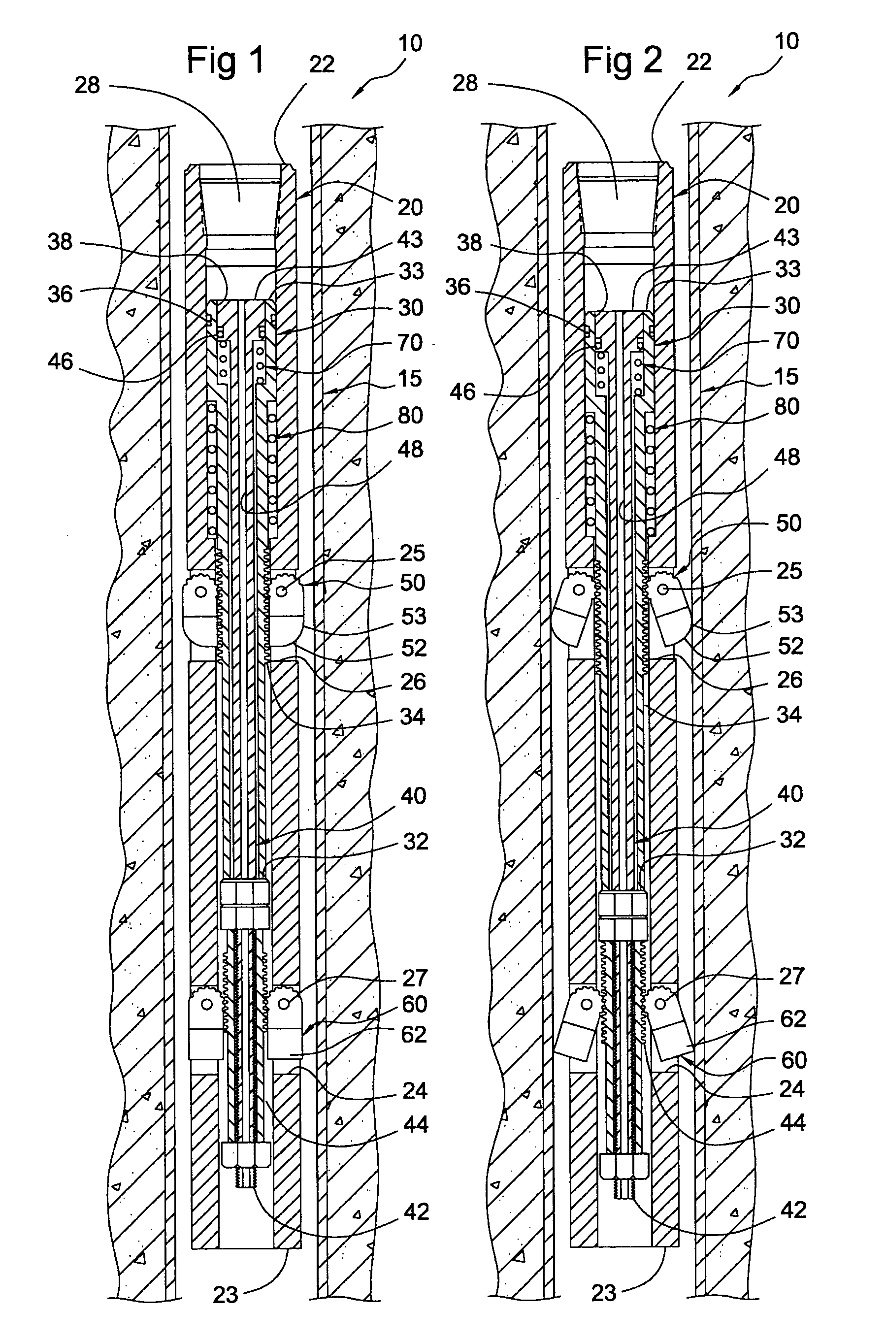
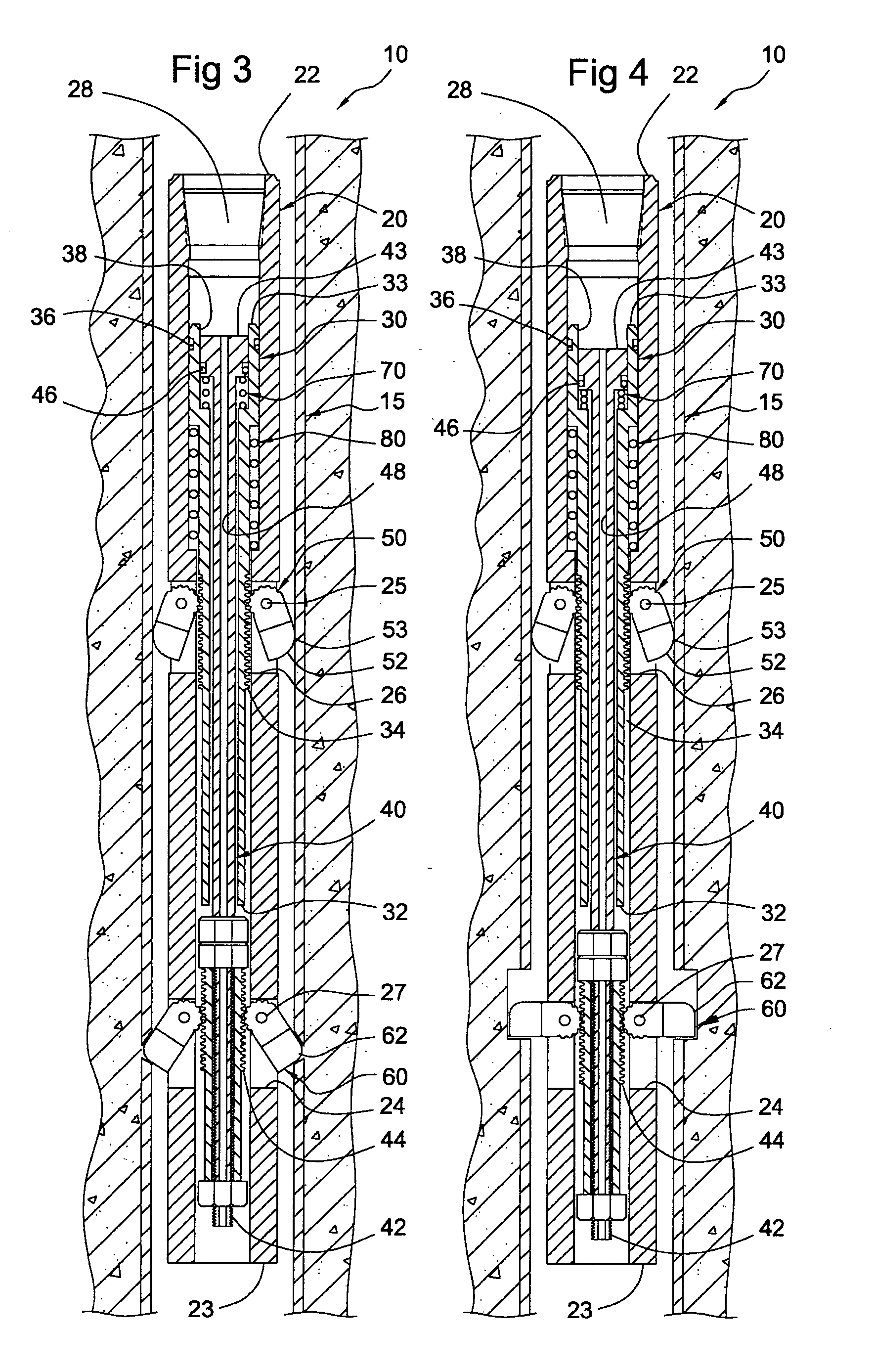
[0031]Referring now to the drawings, where the present invention is generally referred to with numeral 10, it can be observed that it basically includes casing 15, cylindrical assembly 20, tubular shaft assemblies 30 and 40 and first and second sets of blades 50 and 60, and their respective spring bias assemblies 70 and 80.

[0032]An oil well bore typically includes casing 15 that extends downwardly several thousand meters. Sometimes a portion collapses making it inoperational. Rather than closing the oil well and wasting the associated infrastructure investment, a portion of the casing above the problem area is sectioned and branched out to reach oil deposits through a different path. With the present invention, the second set of blades is deployed and used after the first set has been worn out completely. In sum, the cutting and reliability capabilities of the section mill is extended.

[0033]In FIG. 1, the tool subject of the present application is shown within an oil well casing, as...


PUM


Abstract

A section mill for casings used in oil wells to cut predetermined portions for repair purposes. An elongated cylindrical assembly is inserted through the casing and it includes at least two spaced apart apertures with one blade member pivotally mounted within each aperture. First and second coaxially disposed tubular shaft assemblies with teethed portions to coact with the blades to selectively move them between two extreme position upon the application of a pressurized fluid. The fluid needs to overcome the spring biased applied to the shaft assemblies. The first set of blades is stopped and slidably rotates in contact with the internal surface of the casing. The second set cuts through the casing with one end and sections the casing with the other end. After wearing off, the first set of blades continues the sectioning work.

Description

BACKGROUND OF THE INVENTION[0001]1. Field of the Invention[0002]The present invention relates to a section mill for wells, and more particularly, to a section mill that permits a user to extend the cutting performance of the apparatus without retrieving it from the well.[0003]2. Description of the Related Art[0004]In the operation of oil wells, it is common during the maintenance stage to abandon the deepest portion of the casing (when it is in poor conditions) and open a casing window to install a new casing portion, typically, at an angle with respect to the previous casing, to reach oil deposits through a new path. Section mills are utilized to mill portions of a casing to accomplish this. In doing so, the casing needs to be cut from inside the casing and, subsequently, longitudinally reduced. The blades wear off and the conventional mills need to be retrieved to replace the blades and reinsert the mill.[0005]Many designs for section mills have been designed in the past. The pres...

Claims


Application Information

Patent Timeline
IPC IPC(8): E21B29/00E21B10/00E21B10/66
CPCE21B29/005
Inventor PIETROBELLI, ALEJANDROPIETROBELLI, FAUSTO
Owner MECOL OIL TOOLS
Why Eureka
Try Eureka