Wheel-support rolling bearing unit

a technology of rolling bearings and supporting parts, which is applied in the direction of manufacturing tools, heat treatment equipment, furniture, etc., can solve the problems of inability to solve the cutting property and drilling property of materials, and the possibility of metal fatigue cracks and other problems, to achieve the effect of increasing the cutting property, reducing the deformation, and reducing the localization

Inactive Publication Date: 2005-06-30
NSK LTD
View PDF6 Cites 35 Cited by
  • Summary
  • Abstract
  • Description
  • Claims
  • Application Information

AI Technical Summary

Benefits of technology

[0138] In the cylindrical portion of the hub ring being the crimped portion, the material flow and the banded structure are developed in the longitudinal direction by hot forging. Moreover, when the cylindrical portion is expanded by swaging, it is flared in both directions of the perpendicular direction and the circumferential direction so that a force in the longitudinal direction acts with respect to the banded structure. Consequently the material property differs for the portions connected by the pearlite structure and the portions connected by the ferrite structure, even elongation property of the material can not be obtained, and deformability is extremely and locally decreased, so that cracks are easily generated on the crimped portion surface.
[0139] Furthermore, since MnS in steel is a soft inclusion, it has the effect of increasing the cutting property. On the other hand, cracks are easily generated from MnS as the starting point if a tensile stress acts in the perpendicular direction. Moreover, the precipitated amount of MnS is normally determined by the S concentration. However, since the distribution greatly differs depending on the forge ratio and the Mn segregation state, the problems of cracking due to swaging can not be solved by merely controlling the S concentration. The conclusion was thus reached that it is important to control the Mn segregation which determines the size and the distribution of the precipitated MnS.
[0140] Similarly to the austenite grain boundary, the boundary face of MnS and austenite becomes the nucleation site of pro-eutectoid ferrite at the time of cooling after forging. As a result, a structure having MnS in the ferrite is easily formed. In such a structure, voids are formed in the boundary face at the time of cold deformation so that the elongation and reduction value is greatly deteriorated. Accordingly, it is necessary to decrease the boundary faces of ferrite and MnS as much as possible in order to increase the swaging property.

Problems solved by technology

Accordingly, if no countermeasures are taken, damage such as cracks are possibly produced based on the metal fatigue.
Moreover, since a torsional stress is applied to the flange 6 accompanied with the rotation of the wheel, if this flange is the non-thermal refined portion, damage such as cracks is easily produced also in this flange 6.
However, in the flanged bearing unit described in the abovementioned Japanese Unexamined Patent Publication No. 2002-200314, problems with the cutting property and the drilling property of material have not been solved.
If the cutting property and the drilling property are poor, the productivity and the tool life are decreased, being a factor for increasing the cost.
However, if the C amount is decreased, there is a problem of decreasing the rolling fatigue life of the induction hardened raceway 13.
However, when such swaging is performed, there has been a problem of cracking in the radial direction on the surface.
However, the abovementioned problems can not be solved in some cases if the deformation load and the deformation velocity when swaging is increased.

Method used


Image

  • Wheel-support rolling bearing unit
  • Wheel-support rolling bearing unit
  • Wheel-support rolling bearing unit

Examples


first embodiment

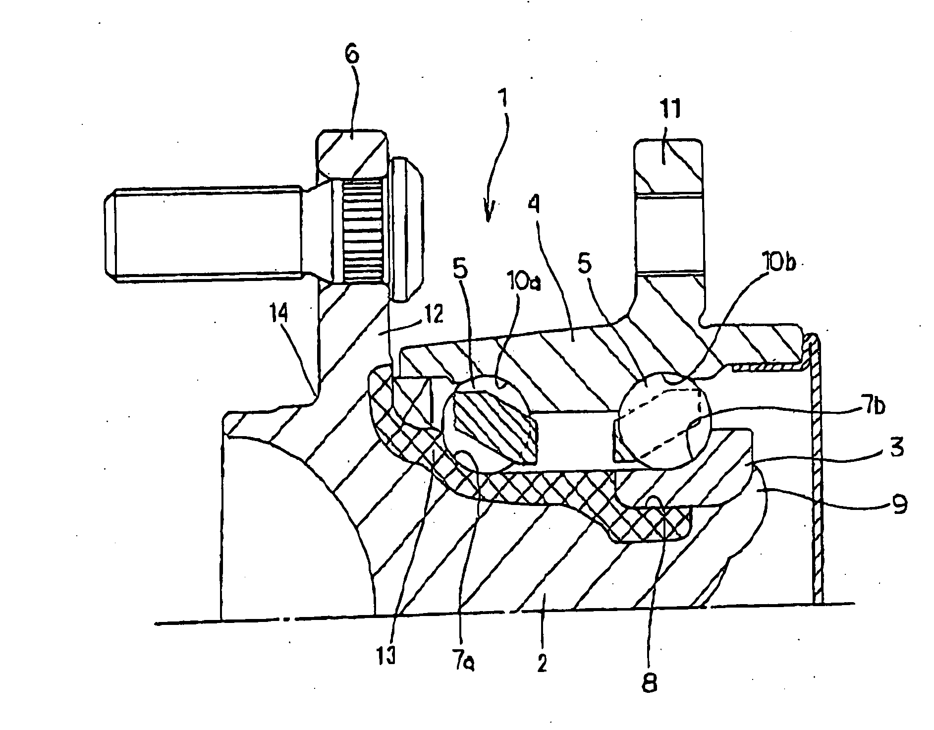
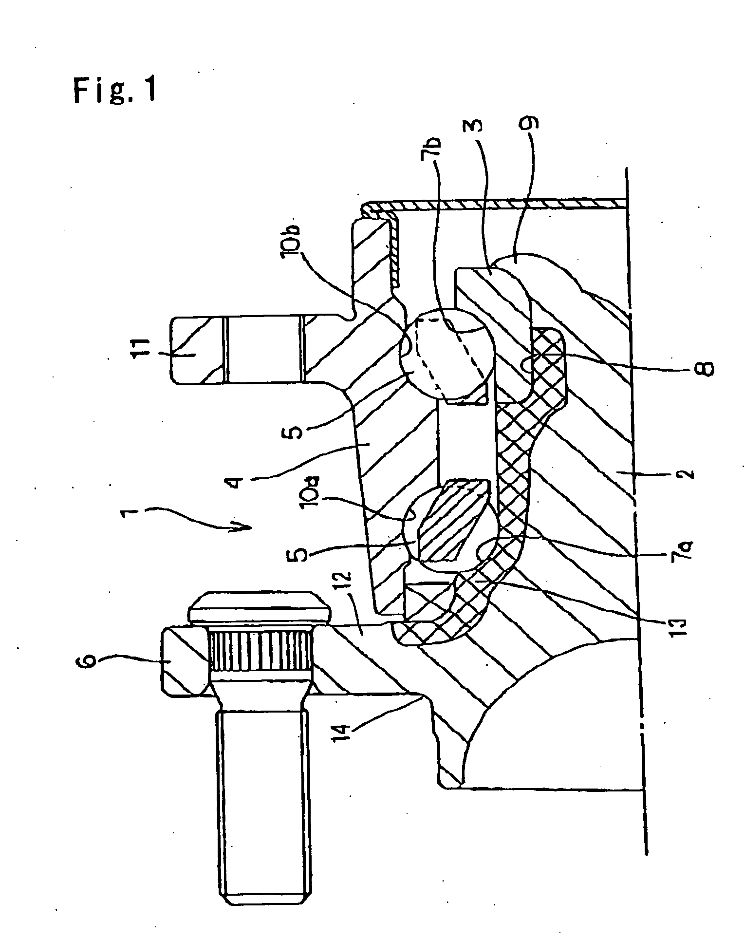
[0226] In the flanged bearing unit 1, since a radial load is produced from the road surface to the bearing while the hub ring 2 is rotating, the rotating bending stress is generated in the root portion of the wheel attaching flange 6. Particularly, at the outside root portion 14 of the wheel attaching flange 6, heat treatment such as quenching and hardening is not applied, but the rotating bending stress is concentrated. Therefore there is concern of damage occurring, depending on the use conditions and design conditions.

[0227] On the other hand, as described above, since it is required to lighten the hub ring 2, it is desirable to thin the wall of the wheel attaching flange 6. However, in order to proceed to thin the wall of the wheel attaching flange 6, it is required to increase the fatigue strength of the outside root portion 14 of the wheel attaching flange 6.

[0228] In the outside root portion (untempered steel) 14 of the wheel attaching flange 6 which is a medium carbon stee...

example a

First Example

[0274] In order to verify the effect of the present invention, the materials shown in Table 7 were used and worked in various hot forging conditions. Then the microstructures were identified, and the amount of the pro-eutectoid ferrite structure was measured by image analysis.

TABLE 7SteelCSiMnCrVSType(Weight %)(Weight %)(Weight %)(Weight %)(Weight %)(Weight %)S53C0.530.210.750.1700.017A10.540.240.790.1500.013A20.530.220.810.1600.005A30.450.220.810.1600.013A40.650.220.810.1600.013A50.560.240.790.150.080.013B10.540.230.870.1500.022B20.430.230.870.1500.013B30.680.230.870.1500.013

[0275] Regarding the hot forging, a steel bar was cut then high frequency induction heating was applied at various temperature between 950 and 1200° C. to change the fine level of the structure. Then hot forging, mainly comprising upsetting was applied and the forging was cooled at various cooling rates so as to make various precipitating conditions of the pro-eutectoid ferrite structure.

[0276]...

second example

[0299] In order to verify the effect of the present invention, the following experiment was performed.

[0300] Firstly, bar-shaped materials having the A to D components in Table 9 were used. The respective bar-shaped materials were cut then high frequency induction heating was respectively applied to give temperatures between 950 and 1200° C. They were then finished into predetermined shapes by hot forging. After that, forced air cooling or radiational cooling was performed and the oxide film was removed by shot blasting. Lathe turning, induction hardening and polishing of the raceway surface were then performed so as to produce the hub ring 2 shown in FIG. 9.

[0301] The hub rings 2 of examples 22 to 30 and comparative examples 7 to 11 in Table 10 were prepared. Moreover, the hub rings 2 of examples 22 to 30 used those for which the abovementioned distribution control of the pro-eutectoid ferrite had been performed.

TABLE 9CSiMnCrVComponent(weight %)(weight %)(weight %)(weight %)(w...


PUM

PropertyMeasurementUnit
arithmetic average roughness Raaaaaaaaaaa
heightaaaaaaaaaa

Abstract

In a wheel-support rolling bearing unit, in order to made a flange 6 thinner and thus lighten the bearing unit without impairing fatigue strength, machinability, and workability after forging, the composition of the alloy steel constituting the flange attached member (hub ring 2), the surface hardness of the root portion 14 on the axial outside surface side of the flange 6, and the surface roughness, are stipulated to thereby improve the durability ratio (fatigue limit strength/tensile strength) of the flange 6. In one aspect, the member is made from an alloy steel containing C: 0.5 to 0.65 weight %, Mn: 0.3 to 1.5 weight %, Si: 0.1 to 1.0 weight %, Cr: 0.01 to 0.5 weight %, S: 0.35 weight % or less, and any one type or more selected from 0.01 to 0.2 weight % of V, 0.01 to 0.15 weight % of Nb, and 0.01 to 0.15 weight % of Ti, with the rest being Fe and inevitable impurities, and the oxygen contents is 15 ppm or less. Moreover, the surface hardness of the inner raceway 7a formed with the hardened layer, is between Hv 650 and 780, and the surface hardness of a portion not formed with the hardened layer is between Hv 230 and 300.

Description

CROSS-REFERENCE TO RELATED APPLICATION [0001] This application is a continuation of an International Application No. PCT / JP03 / 08977 which was filed on Jul. 15, 2003 and claims priority from Japanese Patent Applications 2002-205632 filed on Jul. 15, 2002, 2002-246103 filed on Aug. 27, 2002, 2002-251216 filed on Aug. 29, 2002, 2002-263944 filed on Sep. 10, 2002, 2002-284888 filed on Sep. 30, 2002, 2002-336628 filed on Nov. 20, 2002, 2003-002006 filed on Jan. 8, 2003, 2003-013632 filed on Jan. 22, 2003, 2003-019142 filed on Jan. 28, 2003 and 2002-167239 filed on Jun. 12, 2003, all of which are herein incorporated by reference.TECHNICAL FIELD [0002] The present invention relates to an improvement of a rolling bearing unit for rotatably supporting an automobile wheel with respect to a suspension device. Particularly, it relates to an improvement of a rolling bearing unit which has a flange for fastening the wheel or a part of the suspension device to the peripheral surface, and comprises...

Claims


Application Information

Patent Timeline
Patent Type & Authority Applications(United States)
IPC IPC(8): B60B27/00B60B27/02B60B35/18C21D9/40C22C38/02C22C38/04C22C38/08C22C38/18C22C38/24F16C19/18F16C33/62F16C33/64
CPCB60B27/00Y10T29/49679C22C38/002C22C38/02C22C38/04C22C38/18C22C38/24C22C38/26C22C38/28F16C33/64Y02T10/86F16C19/185F16C19/186Y10S384/913C21D9/40F16C2326/02
Inventor UYAMA, HIDEYUKIMIYAMOTO, YUUJIOKITA, SHIGERU
Owner NSK LTD
Why Eureka
Try Eureka