Indexable Type Cutting Tool

a cutting tool and indexable technology, applied in the direction of shaping cutters, manufacturing tools, twist drills, etc., can solve the problems of inability to ensure precise setting, inability to machining precision but be degraded when compared to the conventional solid-type drilling tool, and inability to accurately and precisely set, etc., to achieve simple, fast and precise fastening, the effect of reducing the manufacturing cost of the tool

Inactive Publication Date: 2008-01-03
KORLOY
View PDF16 Cites 36 Cited by
  • Summary
  • Abstract
  • Description
  • Claims
  • Application Information

AI Technical Summary

Benefits of technology

[0016] By the features of the present invention, the indexable type cutting tool according to the present invention provides advantages in that, since an insert can be simply, quickly and precisely fastened to a tool body and the through-hole of the insert is modified in its profile so that the rotation center of the insert can easily correspond to the rotation center of the tool body, a manufacturing cost of the tool can be reduced due to easy manufacture of the tool, and it is possible to secure a sufficient chip discharge space, thereby improving a cutting performance of the tool.

Problems solved by technology

However, the conventional indexable type cutting tool suffers from defects as described below.
First, when fastening the cutting insert to the drill body, due to misalignment of the centers between the drill body and the cutting insert, precise setting cannot be ensured, whereby a machining precision cannot but be degraded when compared to the conventional solid type drilling tool.
Second, in order to precisely set the rotation centers of the cutting insert and the drill body, because a separate centering device is needed, a procedure for manufacturing the indexable type cutting tool is complicated, and a manufacturing cost increases.
Third, when coupling the cutting insert to the drill body, it is difficult to administrate an assembling precision.

Method used


Image

  • Indexable Type Cutting Tool
  • Indexable Type Cutting Tool
  • Indexable Type Cutting Tool

Examples


first embodiment

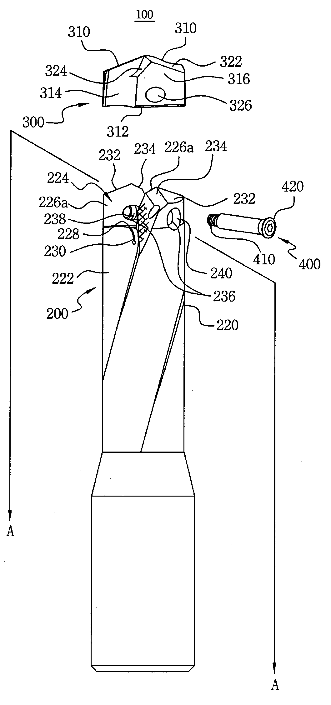
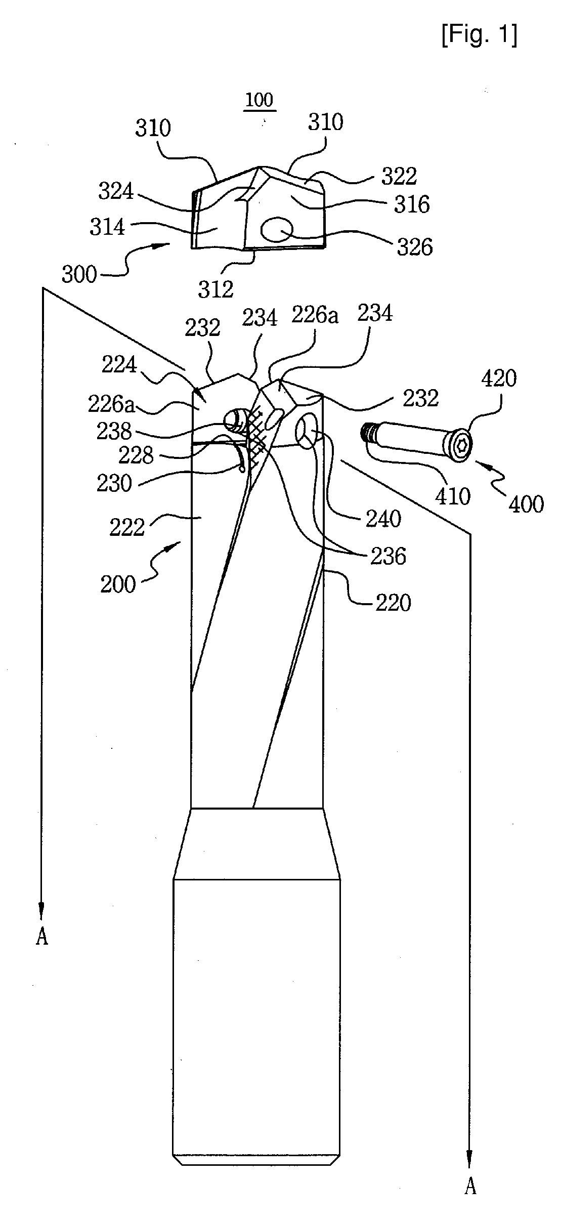
[0034]FIG. 1 is an exploded perspective view illustrating an indexable type cutting tool in accordance with the present invention. The following descriptions will be given on the assumption that the upper end of the drawing indicates a distal end, the lower end of the drawing indicates a proximal end, the left side of the drawing indicates one side, and the right side of the drawing indicates the other side.

[0035] As shown in the drawing, the indexable type cutting tool 100 in accordance with the first embodiment of the present invention comprises a drill 200 which is usually mounted to an arbor (not shown) of a machine tool (not shown), a drill insert 300 which is locked to the distal end of the drill 200 to actually cut a ferrous or non-ferrous metal, and a fastening screw 400 for locking the drill insert 300 to the distal end of the drill 200.

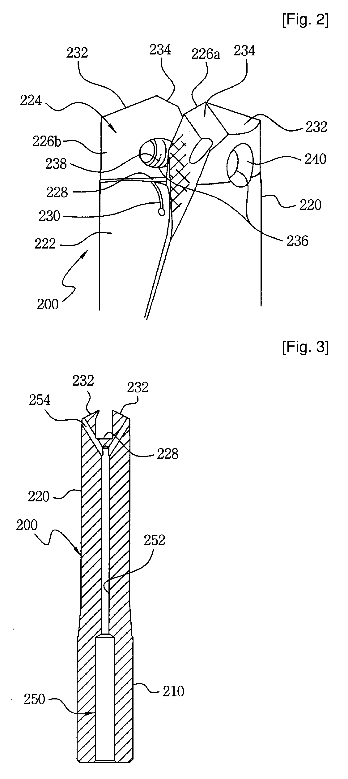
[0036]FIG. 2 is an enlarged view illustrating the distal end of the drill body shown in FIG. 1.

[0037] Referring to FIGS. 1 and 2, the dri...

second embodiment

[0061]FIG. 17 is an exploded perspective view illustrating an indexable type cutting tool in accordance with the present invention, FIG. 18 is an enlarged view illustrating a through-hole of the drill insert shown in FIG. 17, and FIGS. 19 and 20 are views illustrating variations of the through-hole shown in FIG. 18.

[0062] Referring to FIGS. 17 through 20, the indexable type cutting tool 500 in accordance with the second embodiment of the present invention comprises an end mill 600 which is usually mounted to an arbor (not shown) of a machine tool (not shown), an end mill insert 700 which is locked to the distal end of the end mill 600 to actually cut a ferrous or non-ferrous metal, and a fastening screw 800 for locking the end mill insert 700 to the distal end of the end mill 600.

[0063] An insert seat 610 for accommodating the end mill insert 700 is formed on the distal end of the end mill 600. The insert seat 610 has seat side surfaces 612 which face each other and a seat bottom s...


PUM

PropertyMeasurementUnit
angleaaaaaaaaaa
angleaaaaaaaaaa
shapeaaaaaaaaaa

Abstract

An indexable type cutting tool comprises a drill having a shank and a drill body which extends from the shank, the drill body being defined with body flutes, and being formed with an insert seat which has seat side surfaces and a seat bottom surface and body flank surfaces and body thinning surfaces; a drill insert fitted into the insert seat of the drill body, having cutting edges and an insert bottom surface which is brought into close contact with the seat bottom surface, formed with insert flutes and insert side surfaces which are brought into close contact with the seat side surfaces, and defined with a through-hole which passes through the insert side surfaces; and a fastening screw for fastening the drill insert fitted into the insert seat to the drill.

Description

TECHNICAL FIELD [0001] The present invention relates to a drill or a ball end mill among indexable type cutting tools. More particularly, the present invention relates to an indexable type cutting tool wherein an insert can be simply, quickly and precisely fastened to a tool body, and the through-hole of the insert is modified in its profile so that the rotation center of the insert can easily correspond to the rotation center of the tool body, whereby a manufacturing cost of the tool can be reduced due to easy manufacture of the tool, and it is possible to secure a sufficient chip discharge space, thereby improving a cutting performance of the tool. BACKGROUND ART [0002] As generally known in the art, cutting tools are used to cut ferrous metals, non-ferrous metals, and nonmetallic materials. The cutting tools are mounted to machine tools to cut a workpiece into a desired shape. Usually, a cutting tool is composed of a cutting insert which has cutting edges and a tool body to which...

Claims


Application Information

Patent Timeline
Patent Type & Authority Applications(United States)
IPC IPC(8): B23B51/02
CPCB23B51/0009Y10S408/713B23B51/06B23B2251/082B23B2251/14B23B2251/50B23B2260/016B23B2270/08Y10T407/192Y10T408/455Y10T408/9097Y10T408/90993Y10T407/1936Y10T408/89B23B51/02B23B51/00035B23B51/00
Inventor KIM, YOUNG-HEUMKIM, JOO-OHLEE, KWAN-HEEKIM, HAK-KYU
Owner KORLOY
Why Eureka
Try Eureka