
Rotary cutting tool with non-uniform distribution of chip-breaking features

a rotary cutting tool and feature technology, applied in shaping cutters, manufacturing tools, wood boring tools, etc., can solve the problems of non-uniform distribution of chip-breaking features, tool not subject to significant uniform periodic forces, and material being machined at any given position is not subject to a uniform pattern, etc., to enhance the cutting performance of the rotary cutting tool, save valuable machining time, and reduce material consumption

Active Publication Date: 2009-06-09
BERKSHIRE PRECISION TOOL
View PDF26 Cites 35 Cited by
  • Summary
  • Abstract
  • Description
  • Claims
  • Application Information

AI Technical Summary

Benefits of technology

[0015]Another advantage of the present invention rotary cutting tool is that chip-breaking features that can remove material away from the tool aggressively (i.e., “rough” the material out) can be combined with chip-breaking features that remove less material, but leave an acceptable fine finish. As a result, a machining operation that may have historically required two separate cutting tools can now be done with one, thereby saving valuable machining time.
[0016]Another advantage of the present invention rotary cutting tool is that the chip-breaking features (sometimes referred to as “chip breakers”, “knuckles” or “notches”) generate a positive relief at the cutting edges, leading face edges, and trailing face edges and thereby significantly enhance the cutting performance of the rotary cutting tool.
[0017]Another advantage of the present invention rotary cutting tool is that the loading per blade for a given set of operating conditions can be “tuned” to minimize undesirable harmonic response and optimize the performance of the rotary cutting tool.
[0018]In sum, the present invention rotary cutting tool gives rise to a number of advantages which manifest themselves in superior performance, highly improved wear characteristics, ease of manufacture and relatively simple maintenance. The latter arises because the cutting tool of the invention is provided with a positive rake relief angle of the cutting edges, and positive relief angles of the trailing and leading edges of the cutting blade, and while having a non-conventional form, may nevertheless be sharpened and reground with conventional equipment.
[0019]It is, of course, to be understood that the present invention is by no means limited to the particular construction shown in the accompanying drawings, but also encompasses many modifications within the scope of the appended claims. For example, as previously noted, the invention has been shown in conjunction with a spirally fluted cutting tool. However, the invention may also be useful with other forms of cutting tools, such as straight fluted cutting tools, tapered cutting tools, variable helix cutting tools, variable index cutting tools and, indeed, may be applicable to still other types of rotary cutting tools. Further, it will be appreciated that such cutting tools may vary considerably in diameter and size, and that the depth of cut of the flute employed during construction of the cutting tool may vary considerably depending upon the desired cutting edge.
[0020]These and other features and advantages of the present invention will become apparent in light of the drawings and detailed description of the present invention provided below.

Problems solved by technology

The pattern of non-uniformly distributed chip-breaking features is such that the material being machined at any given position is not subject to a uniform pattern of features as the tool rotates.
As a result, the tool is not subject to significant uniform periodic forces that could give rise to an undesirable harmonic response under acceptable operating conditions.
The blades adjacent one another have loading values of different magnitudes to prevent or minimize the tool being subject to significant uniform periodic forces that could give rise to an undesirable harmonic response to the aforesaid operating conditions.
Aggressive machining with many prior art rotary cutting tools is not practically possible, however, because it creates undesirable harmonic responses (i.e., vibrations) within the tool.

Method used


Image

  • Rotary cutting tool with non-uniform distribution of chip-breaking features
  • Rotary cutting tool with non-uniform distribution of chip-breaking features
  • Rotary cutting tool with non-uniform distribution of chip-breaking features

Examples


Embodiment Construction

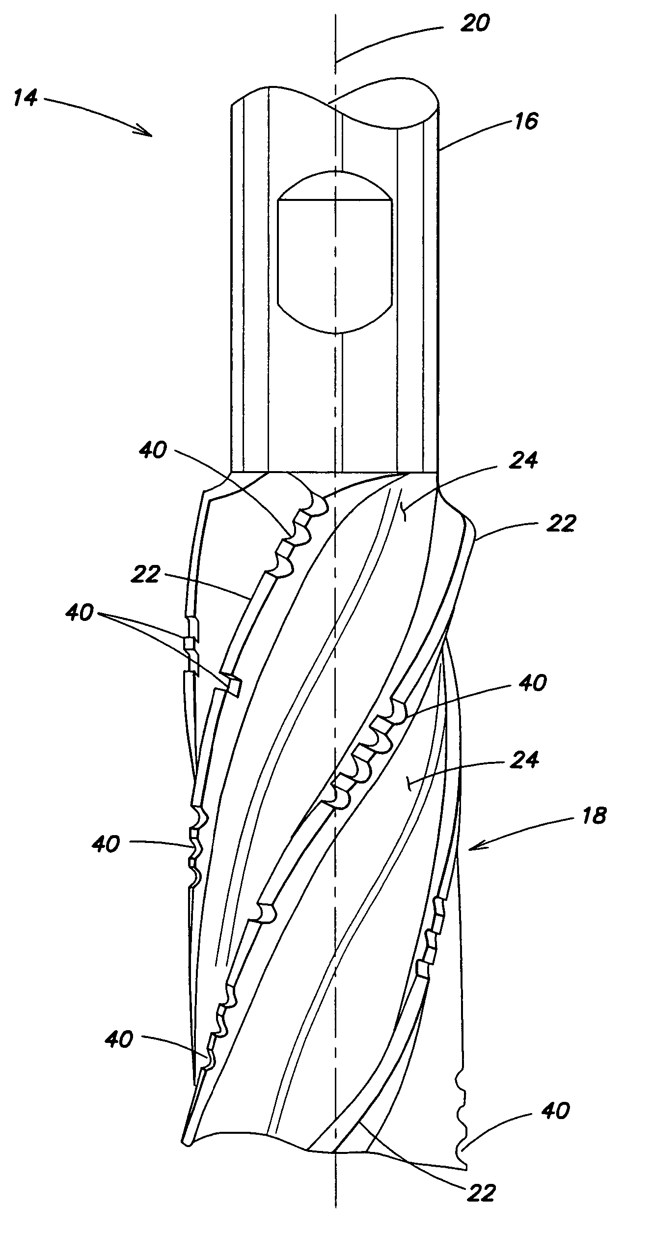
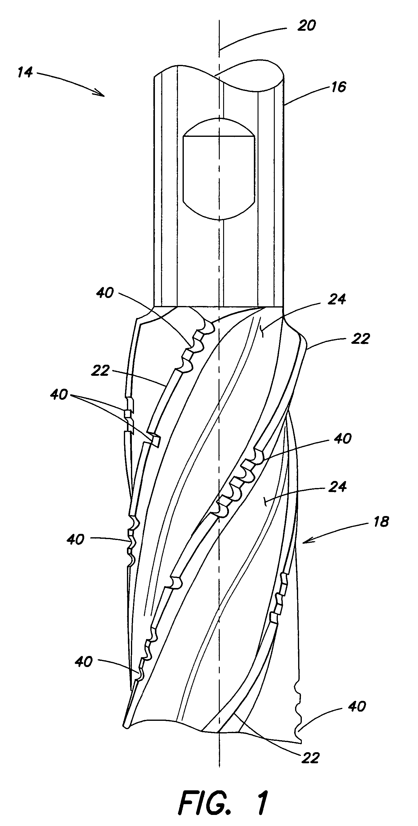
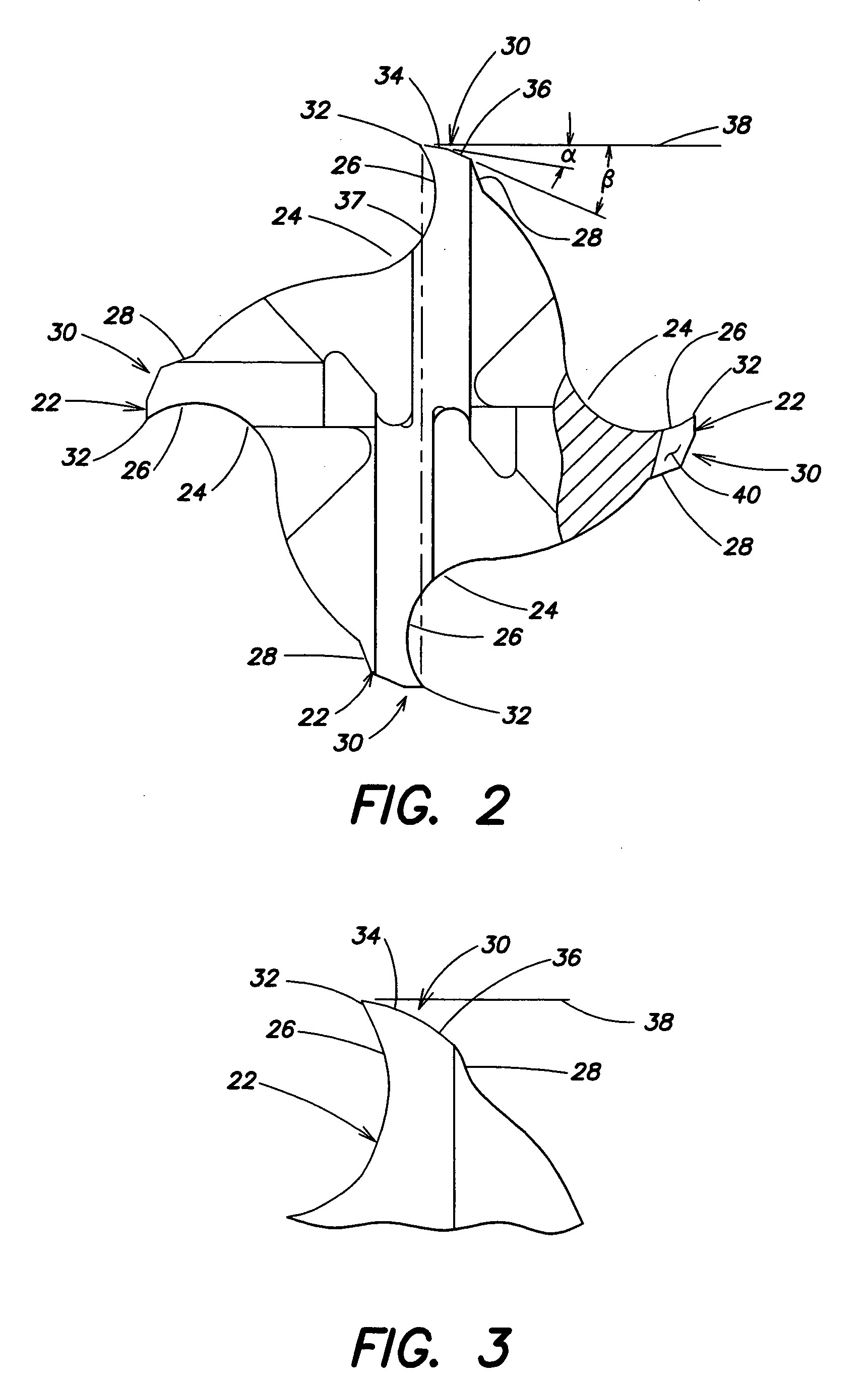
[0033]Now referring to FIGS. 1-3, a rotary cutting tool 14 is provided that includes a shank portion 16, a cutting portion 18, and a longitudinal axis 20. The overall shape of the cutting portion 18 may be, but is not limited to, a cylindrical shape or a frustoconical shape (e.g., see FIG. 12). The cutting portion 18 includes a plurality of blades 22 separated by flutes 24 extending the length of the cutting portion 18. Each of the blades 22 has a leading face side 26, a trailing face side 28, and a land surface 30 bridging the leading face side 26 and trailing face side 28. The intersection between the leading face side 26 and the land surface 30 forms a cutting edge 32 for the respective blade 22. In some embodiments, the blades 22 and flutes 24 of the cutting portion 18 extend helically within the cutting portion 18, and in other embodiments, the blades 22 and flutes 24 are “straight flutes” that extend parallel to the longitudinal axis 20.

[0034]In some embodiments the land surfa...


PUM

PropertyMeasurementUnit
lengthaaaaaaaaaa
distanceaaaaaaaaaa
constant radiusaaaaaaaaaa

Abstract

A rotary cutting tool with a longitudinal axis is provided that includes a shank portion, a cutting portion, and a plurality of chip-breaking features. The cutting portion, which extends out from the shank portion, includes a length, a plurality of blades and a plurality of flutes. The blades and flutes extend substantially all of the length of the cutting portion. Each blade includes a leading face side, a trailing face side, and a land surface that extends between the leading face side and the trailing face side. The plurality of chip-breaking features are disposed in the land surfaces of the blades, and non-uniformly distributed among the blades.

Description

BACKGROUND OF THE INVENTION[0001]1. Field of the Invention[0002]The present invention relates to rotary cutting tools in general, and to rotary cutting tools having chip-breaking features in particular.[0003]2. Background Information[0004]Rotary cutting tools such as end mills typically have a cylindrical configuration that includes a shank portion and a cutting portion. The cutting portion contains a plurality of helically disposed cutting blades that extend from a first end (i.e., the “shank end”) of the cutting portion adjacent the shank portion, toward the opposite end (i.e., the “free end”) of the cutting portion. In some embodiments, the cutting edges of the helical blades are disposed along a substantially constant radius with respect to the longitudinal axis of the tool. In other embodiments, generally referred to as “tapered” cutting tools, the cutting portion is substantially frustoconical in shape; i.e., the cutting edge of each blade has a constantly decreasing radius wi...

Claims


Application Information

Patent Timeline
Patent Type & Authority Patents(United States)
IPC IPC(8): B23C5/10
CPCB23C5/003B23C5/10B23C2210/086B23C2210/088B23C2210/486Y10T407/1958Y10T408/9097Y10T407/1946Y10T407/196Y10T407/1948Y10T407/1962
Inventor FLYNN, CLIFFORD M.
Owner BERKSHIRE PRECISION TOOL
Learn More