Cutting insert, cutting tool, and method of manufacturing machined product using the same

a cutting tool and cutting insert technology, applied in the direction of turning machine accessories, manufacturing tools, shaping cutters, etc., can solve the problems of increasing thrust force on the minor cutting edge during cutting, affecting the quality of finished surfaces, so as to reduce the thrust force, reduce the cutting resistance, and increase the cutting resistance. effect of resistan

Active Publication Date: 2012-03-22
KYOCERA CORP
View PDF9 Cites 36 Cited by
  • Summary
  • Abstract
  • Description
  • Claims
  • Application Information

AI Technical Summary

Benefits of technology

[0005]An object of the present invention is to provide a cutting insert, a cutting tool, and a method of manufacturing a machined product using the same, which are capable of forming a superior finished surface.
[0011]In the cutting insert according to the embodiment of the present invention, the minor cutting edge land portion is disposed correspondingly to the minor cutting edge which has a larger peripheral cutting edge angle than the major cutting edge, and therefore the cutting resistance exerted thereon during cutting is likely to increase. The minor cutting edge land portion is inclined downward toward the central part. Therefore, the thrust force can be decreased by relatively decreasing the cutting resistance exerted on the minor cutting edge during the cutting. Consequently, the vibration caused due to the thrust force during the cutting can be effectively reduced, thereby improving the finished surface of the machined product.
[0012]In the cutting insert according to the other embodiment of the present invention, the strength of the part of the minor cutting edge close to the major cutting edge is enhanced by increasing the width at the end portion of the minor cutting edge land portion close to the major cutting edge, and by decreasing the inclination angle thereof. Additionally, the cutting performance of the part of the minor cutting edge close to the flat cutting edge is enhanced by decreasing the width at the end portion of the minor cutting edge land portion close to the flat cutting edge, and by increasing the inclination angle thereof. Thus, the minor cutting edge achieves a satisfactory balance between the strength required for the major cutting edge and the cutting performance required for the flat cutting edge. Therefore, during the general cutting, the cutting can be carried out by the minor cutting edge in addition to the major cutting edge, and the finished surface can be smoothed by the flat cutting edge. On the other hand, during the high feed (high feed rate cutting), the cutting is carried out only by the major cutting edge, and the finished surface can be smoothed by the minor cutting edge instead of the flat cutting edge.

Problems solved by technology

However, the thrust force on the minor cutting edge during cutting increases in these cutting inserts.
Therefore, vibration (chatter phenomenon) is likely to occur during the cutting, and the quality of a finished surface may deteriorate.
Also, it has been difficult for these cutting inserts to conform to a plurality of cutting conditions from general feed to high feed (high feed rate cutting).

Method used


Image

  • Cutting insert, cutting tool, and method of manufacturing machined product using the same
  • Cutting insert, cutting tool, and method of manufacturing machined product using the same
  • Cutting insert, cutting tool, and method of manufacturing machined product using the same

Examples


first embodiment

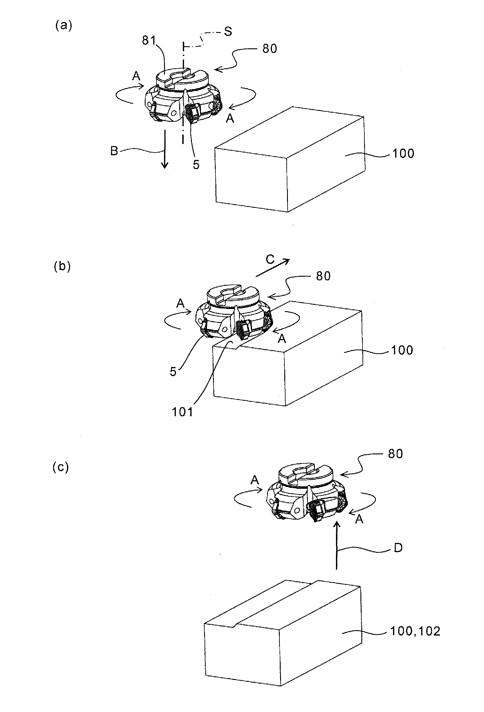
[0083]A first embodiment of the cutting tool according to the present invention is described in detail below with reference to FIGS. 10 and 11. As shown in FIG. 10, the cutting tool 80 (rotary cutting tool) of the present embodiment include a plurality of inserts 1, and a holder 81 configured to attach the plurality of inserts 1 thereto.

[0084]A plurality of insert pockets 82 are formed along the peripheral edge portion of the holder 81. The inserts 1 are respectively attached to peripheral positions in these insert pockets 82. Specifically, each of the inserts 1 is attached so that the major cutting edge 51 is located at the outermost periphery with the upper surface 2 oriented forwardly in the direction of rotation.

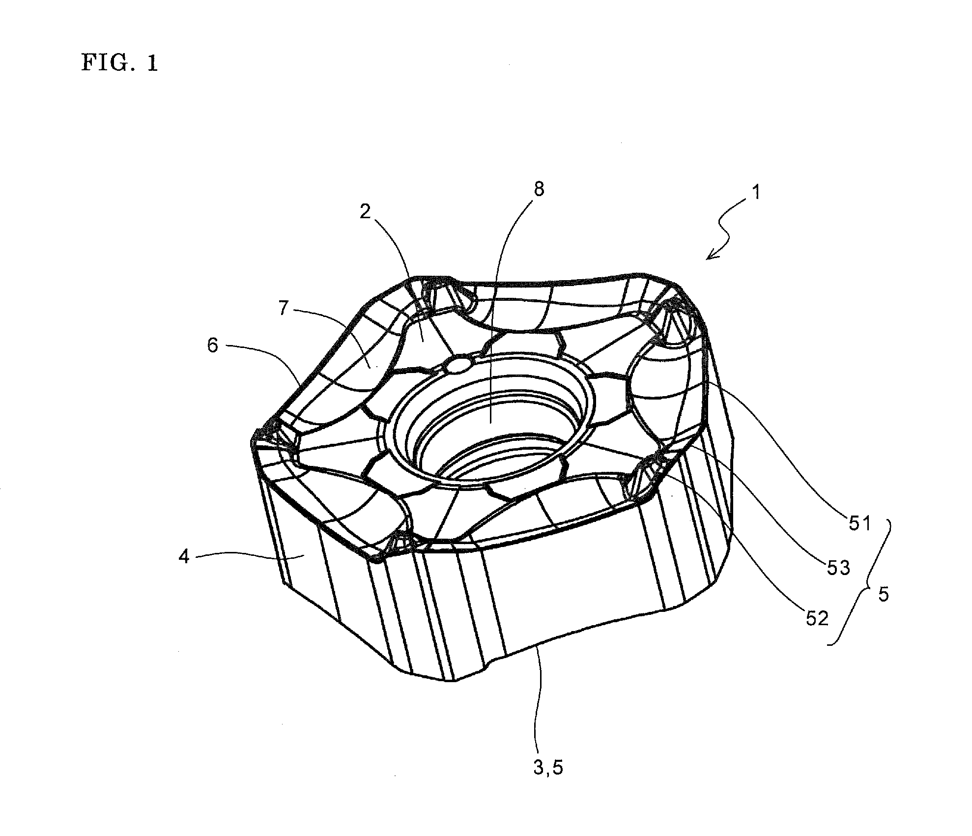
[0085]The attachment is performed, for example, by inserting an attachment screw 84 into an attachment screw contact portion 8 (screw hole) of each of the inserts 1, and then screwing the attachment screw 84 into a female screw formed in an attachment face 83 of the hold...

second embodiment

[0087]A second embodiment of the cutting tool according to the present invention is described in details below with reference to FIGS. 12 and 13. In FIGS. 12 and 13, the components similar to those in FIGS. 10 and 11 are denoted by like reference numerals, and therefore the description thereof is omitted. Referring to FIGS. 12 and 13, the cutting tool 90 of the present embodiment includes a plurality of inserts 11, and a holder 91 configured to attach the plurality of inserts 11 thereto. A plurality of insert pockets 92 are disposed with a gap each other in a circumferential direction along a peripheral edge portion of the holder 91.

[0088]The insert pockets 92 are substantially V-shaped cut-out portions in a flat view, and the inserts 11 are respectively attached to a plurality of attachment faces 93 formed by these cut-out portions. The inserts 11 are attached by orienting the upper surface 12 forwardly in the direction of rotation, and allowing the major cutting edge 151 to protru...

third embodiment

[0092]A third embodiment of the cutting tool according to the present invention is described in details below with reference to FIG. 14. In FIG. 14, the components similar to those in FIGS. 10 to 13 are denoted by like reference numerals, and therefore the description thereof is omitted.

[0093]Referring to FIG. 14, the cutting tool 95 of the present embodiment includes a plurality of inserts 11, and a holder 96 configured to attach the plurality of inserts 11 thereto. The holder 96 has substantially the same configuration as the holder 91 in the second embodiment. In the holder 96, the major cutting edge 151 of each of the inserts 11 contacts against a workpiece 100 at a relatively gentle inclination of approximately 30°.

[0094]The foregoing inserts 11 are also used in the cutting tool 95, thus producing action and effect such as breakage prevention of the corner parts, and elongated life time of the inserts 11. The cutting tool 95 is especially suitable for ultra high feed cutting. T...


PUM

PropertyMeasurementUnit
cutting edge angleaaaaaaaaaa
thicknessaaaaaaaaaa
thicknessaaaaaaaaaa

Abstract

A cutting insert of the present invention includes an upper surface; a lower surface; a side surface; a cutting edge which is located along an intersection of the upper surface and the side surface, and comprises a major cutting edge, a flat cutting edge, and a minor cutting edge located between the major cutting edge and the flat cutting edge; and a land part located along the cutting edge on the upper surface. The land part includes a minor cutting edge land portion located correspondingly to the minor cutting edge. The minor cutting edge land portion is inclined downward toward a central part of the upper surface. The present invention also provides a cutting tool including the cutting insert, and a method of manufacturing a machined product by using the cutting tool.

Description

TECHNICAL FIELD[0001]The present invention relates to a cutting insert, a cutting tool, and a method of manufacturing a machined product using the same.BACKGROUND ART[0002]Conventionally, in a cutting insert including a major cutting edge for cutting a workpiece and a flat cutting edge for smoothing the surface of the workpiece produced by the cutting, a minor cutting edge having a larger peripheral cutting edge angle than the major cutting edge is formed between the major cutting edge and the flat cutting edge from the viewpoint of damage reduction of a cutting edge. For example, Japanese Unexamined Patent Publication No. 2008-6579 discloses a cutting insert in which the angle formed between a major cutting edge and a flat cutting edge is 45°, and an intermediate cutting edge 11 (minor cutting edge) having a larger peripheral cutting edge angle than the major cutting edge is formed between the major cutting edge and the flat cutting edge.[0003]However, the thrust force on the minor...

Claims


Application Information

Patent Timeline
Patent Type & Authority Applications(United States)
IPC IPC(8): B23C5/20B23C5/06B23B27/14
CPCB23C5/06B23C5/202B23C2200/0444Y10T407/1924B23C2200/208Y10T407/23Y10T409/303808B23C2200/201
Inventor ISHI, HIROHISAXU, YONGBO
Owner KYOCERA CORP
Why Eureka
Try Eureka