Integrated reconfigurable manufacturing system

a manufacturing system and reconfigurable technology, applied in the field of integrated reconfigurable manufacturing system, can solve the problems of cnc machine slowness, limited gauges to measuring a small number of dimensions, and a large challenge in reducing floor spa

Inactive Publication Date: 2005-07-26
RGT UNIV OF MICHIGAN
View PDF10 Cites 24 Cited by
  • Summary
  • Abstract
  • Description
  • Claims
  • Application Information

AI Technical Summary

Problems solved by technology

Therefore, the reduction in floor space is an important challenge to the manufacturing industry.
Another challenge is how can one scale up a system production capacity in a cost-effective, rapid method when the market demand increases.
Compared to the dedicated machines, the CNC machines are slow.
Another challenge relates to in-process inspection of parts.
(1) In-process measurement by dedicated mechanical gauges that provide a binary “Good/Not-Good” (or “Go/No-Go”) output. Each time that a different type of parts is produced, these gauges have to be changed. These gauges are limited to measuring a small number of dimensions, and cannot measure such features as surface flatness or parallelism of two surfaces; and
(2) Measureme

Method used


Image

  • Integrated reconfigurable manufacturing system
  • Integrated reconfigurable manufacturing system
  • Integrated reconfigurable manufacturing system

Examples


embodiment 200

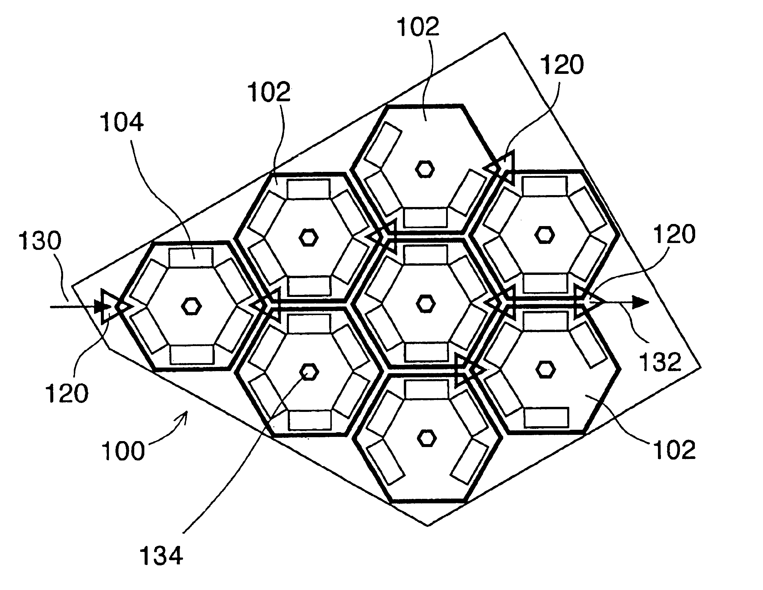
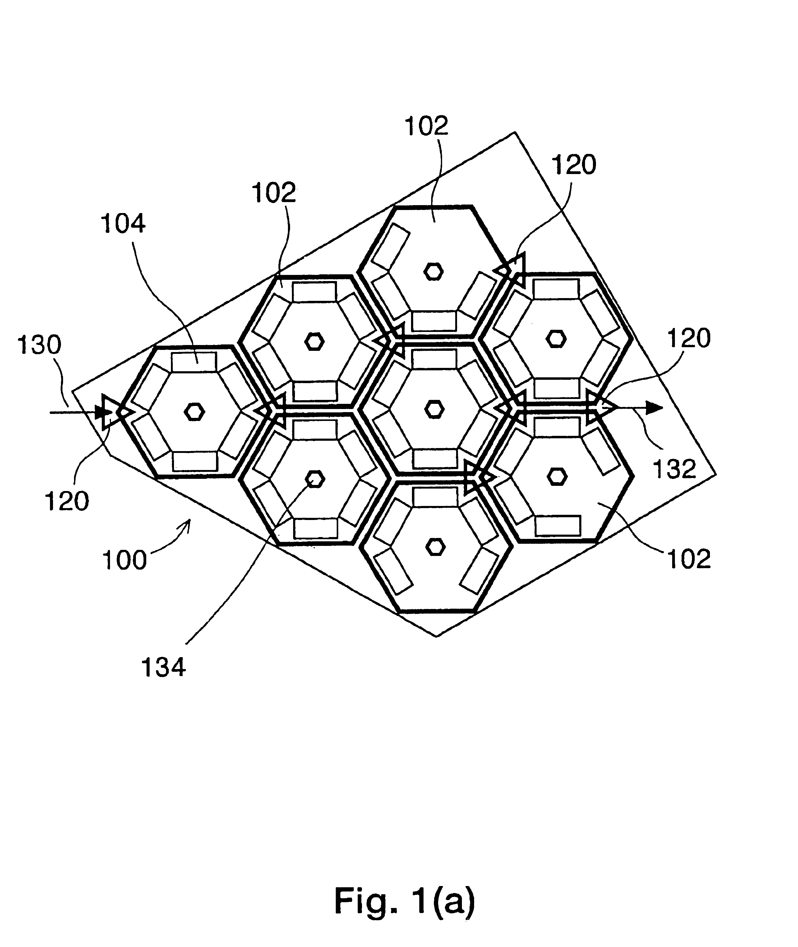
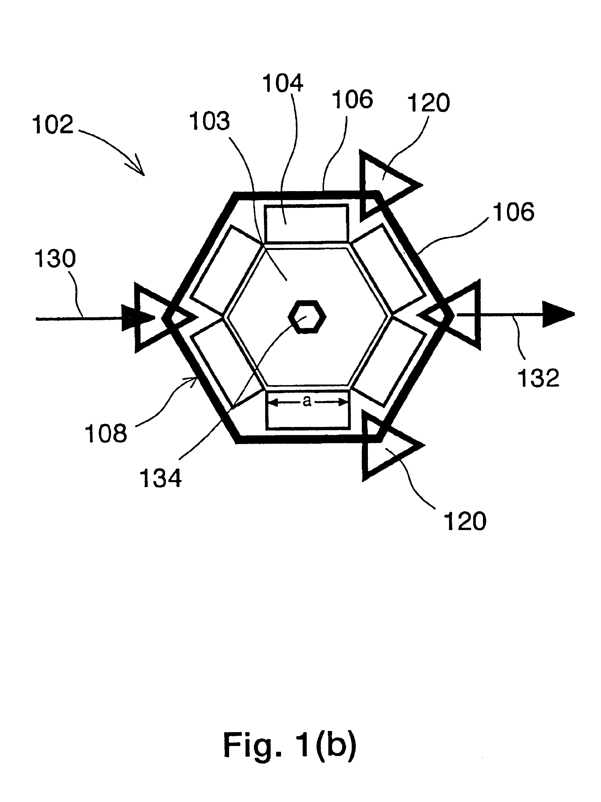
[0047]In this equation, T1 is the traveling time between two successive manufacturing stations 104, p is the distance between the pick-up loop conveyor 120a and the placement loop conveyor 120b, where p is measured in units that correspond to the number of intervening manufacturing stations 104, and T2 is the time to load or unload, i.e. the time to pick up a part 118 from the manufacturing station 104 or from the pick-up loop conveyor 120a, and also the time to place a part 118 on the machine table 114 or on the placement loop conveyor 120b. See FIG. 4(a). Equation 1 is illustrated in FIG. 4(b), where positive p corresponds to clockwise direction and negative p corresponds to counterclockwise direction, and p is the vertex number as marked in FIG. 4(a). The distance p in FIG. 4(a) is p=2. A distance of p=0 means that the pick-up loop conveyor 120a and the placement loop conveyor 120b are the same, yielding the minimum traveling time. Because the loop conveyor 120 may also transfer ...

embodiment 400

[0067]One hexagonal cell 502, for example the cell 502 that is associated with stage 2 of the manufacturing system 500, may contain one or more RMTs 584, each dedicated to the same family of parts. These RMTS 584 may be reconfigured for optimal productivity as explained in connection with embodiment 400. Another cell 502, for example the cell 402 that corresponds to stage 4 may include one or more regional RMTs 586, such as RMTs that are appropriate for the region in which the manufacturing system 500 is installed. Similarly, one of the cells 502, such as the cell 502 that is associated with an inspection stage 6, may contain one or more RIMs 590.

[0068]The honeycomb system 500 has the ability to transfer parts backwards without the need for a backward material transporter. A transfer of a part 118 from stage 6 to stage 1, for example, may be done by transferring the part 118 from a particular loop conveyor 520 designator by γ to another loop conveyor 520 designated by α by taking th...


PUM

PropertyMeasurementUnit
Flexibilityaaaaaaaaaa
Dynamicaaaaaaaaaa

Abstract

An integrated reconfigurable multi-stage manufacturing system and associated methods. The system may include a plurality of manufacturing cells, each cell associated with at least one stage of a manufacturing process. The plurality of cells may include a first cell comprising at least one flexible manufacturing station, a second cell comprising at least one reconfigurable manufacturing station, and a third cell comprising at least one reconfigurable inspection machine. The system may also include a plurality of loop conveyors and a plurality of cell gantries. Each loop conveyor may connect at least two neighboring cells and each cell gantry may transport parts from the cell associated with the cell gantry to at least one loop conveyor. In one embodiment, each cell may be hexagonal, and the manufacturing system may have a honeycomb structure.

Description

FEDERALLY SPONSORED RESEARCH[0001]Certain of the research leading to the present invention was sponsored by the United States Government under National Science Foundation Grant No. EEC-959125. The United States Government has certain rights in the invention.BACKGROUND OF THE INVENTION[0002]The production of many parts and products is done by multi-stage manufacturing systems. At each stage, certain production equipment performs a particular manufacturing operation that may include several tasks. A task may be, for example, drilling a hole or welding a spot, or inserting a pin in a hole. The partly-finished part is transferred from one stage to the next via a material transport system, such as a conveyor, a robot, an autonomous guided vehicle (AGV), an overhead gantry, or by people. This multi-stage production method is typical to medium and high-volume manufacturing of a variety of parts and products ranging from engines, pump housings, appliances, cars, to microprocessors. The spec...

Claims


Application Information

Patent Timeline
IPC IPC(8): B23Q41/00B23Q41/04B23P21/00
CPCB23P21/004B23Q41/04Y10T29/53409Y10T29/53365Y10T29/534Y10T29/49829Y10T29/5124
Inventor KOREN, YORAMHILL, RODNEY L.
Owner RGT UNIV OF MICHIGAN
Why Eureka
Try Eureka