Method for adjusting nozzle gap

a technology of adjusting method and nozzle gap, which is applied in the direction of electrical-based machining apparatus, metal-working apparatus, manufacturing tools, etc., can solve the problems of inability to quickly and accurately adjust the gap, undetectable variation of adjustment, and inability to meet the needs of production and use, etc., to achieve accurate value

Inactive Publication Date: 2005-07-26
FANUC LTD
View PDF10 Cites 5 Cited by
  • Summary
  • Abstract
  • Description
  • Claims
  • Application Information

AI Technical Summary

Benefits of technology

[0009]Accordingly, it is an object of the present invention to solve the above-mentioned problems and to set the gap between the forward end of the upper nozzle and the workpiece to a predetermined distance without the damage which might otherwise be caused by the contact between the machine and the workpiece.
[0020]In the first aspect of the present invention, the forward end of the upper nozzle comes into contact with the spacer member but not into direct contact with the workpiece when adjusting the gap, and therefore the damage to the machine which might otherwise be caused by the direct contact between the workpiece and the forward end of the upper nozzle can be prevented.
[0021]According to a second aspect of the nozzle gap adjusting method of present invention, in at least one of the upper nozzle moving, upper nozzle separating and upper nozzle approximating steps in the first aspect, a distance to be covered by the upper nozzle (i.e., a distance by which the upper nozzle is moved) is corrected, based on a predetermined correction amount. In this aspect of the present invention, the correction is carried out to compensate for the deformation of the upper nozzle, etc. caused by the upper nozzle coming into contact with the spacer member, the displacement of the upper guide due to the pressure of the working fluid, and / or other factors, thereby making it possible to set the gap between the forward end of the upper nozzle and the workpiece to a more accurate value.

Problems solved by technology

In this way, all the jobs for nozzle gap adjustment are carried out manually and, therefore, the problem is posed that such an adjustment consumes much time on the one hand and the result of adjustment is undesirably varied on the other hand.
However, no conventional method is available whereby the gap can be set both rapidly and accurately.
However, in the nozzle apparatus disclosed in the above-described patent, since the forward end of the nozzle is brought into contact with the workpiece and the nozzle position setting is performed with reference to a contact point between the forward end of the nozzle and the workpiece, a problem is encountered that the machine may be damaged by the contact with the workpiece.

Method used


Image

  • Method for adjusting nozzle gap
  • Method for adjusting nozzle gap
  • Method for adjusting nozzle gap

Examples


second embodiment

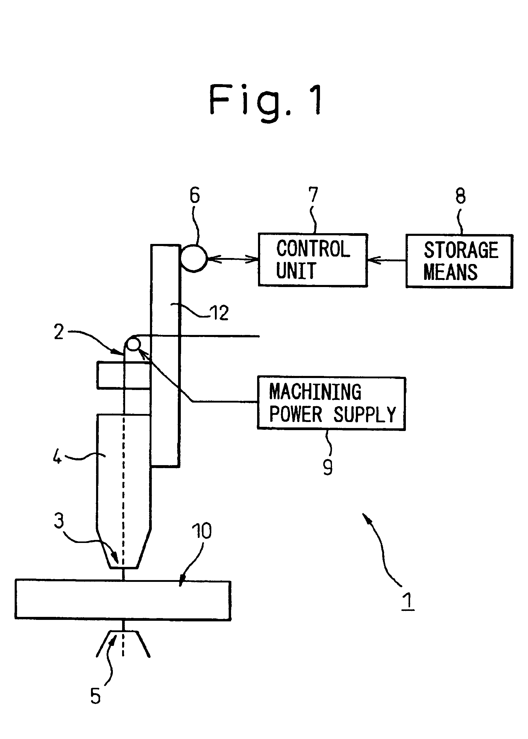
[0055]FIGS. 4A to 4E and 5 are schematic diagrams and a flowchart, respectively, for explaining the steps of the method according to the present invention. In FIGS. 4A to 4E, only the upper nozzle 3, the workpiece 10 and the spacer member 11 are shown, while the remaining parts of the wire EDM 1 is omitted.

[0056]When the forward end of the upper nozzle 3 comes into contact with the spacer member 11, the drive mechanism, the workpiece 10, the upper nozzle 3 and the spacer member 11, etc. are deformed. Also, when the coolant (working fluid) is supplied from the upper guide 4, the upper guide 4 is displaced under the pressure of the working fluid. Such deformation and displacement cause the deviation of the position of the upper nozzle 3. In the method according to the second embodiment of the present invention, the correction is made to compensate for such deformation and displacement in the step of separating the upper nozzle 3 from the workpiece 10 and the spacer member 11.

[0057]In ...

first embodiment

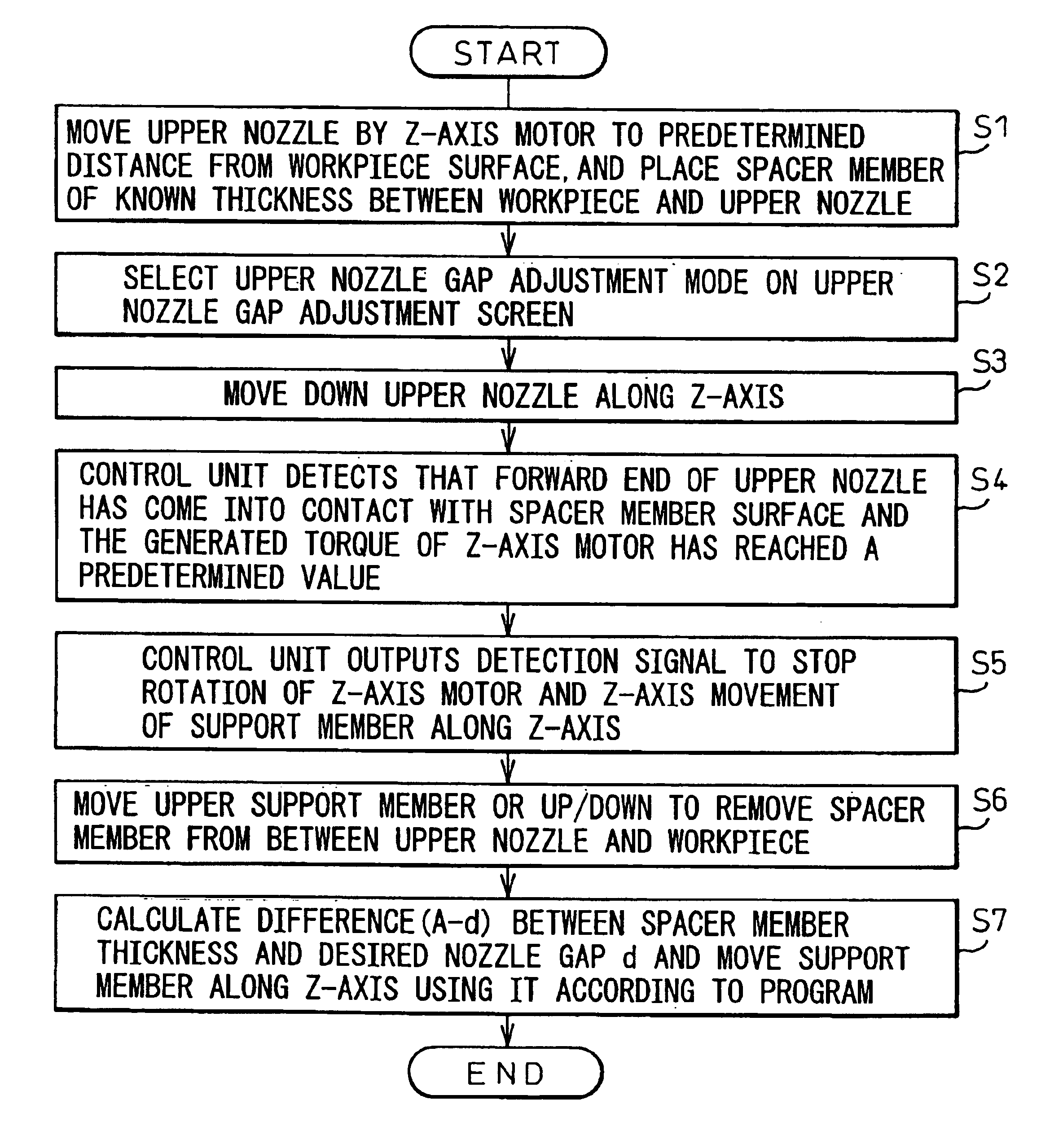
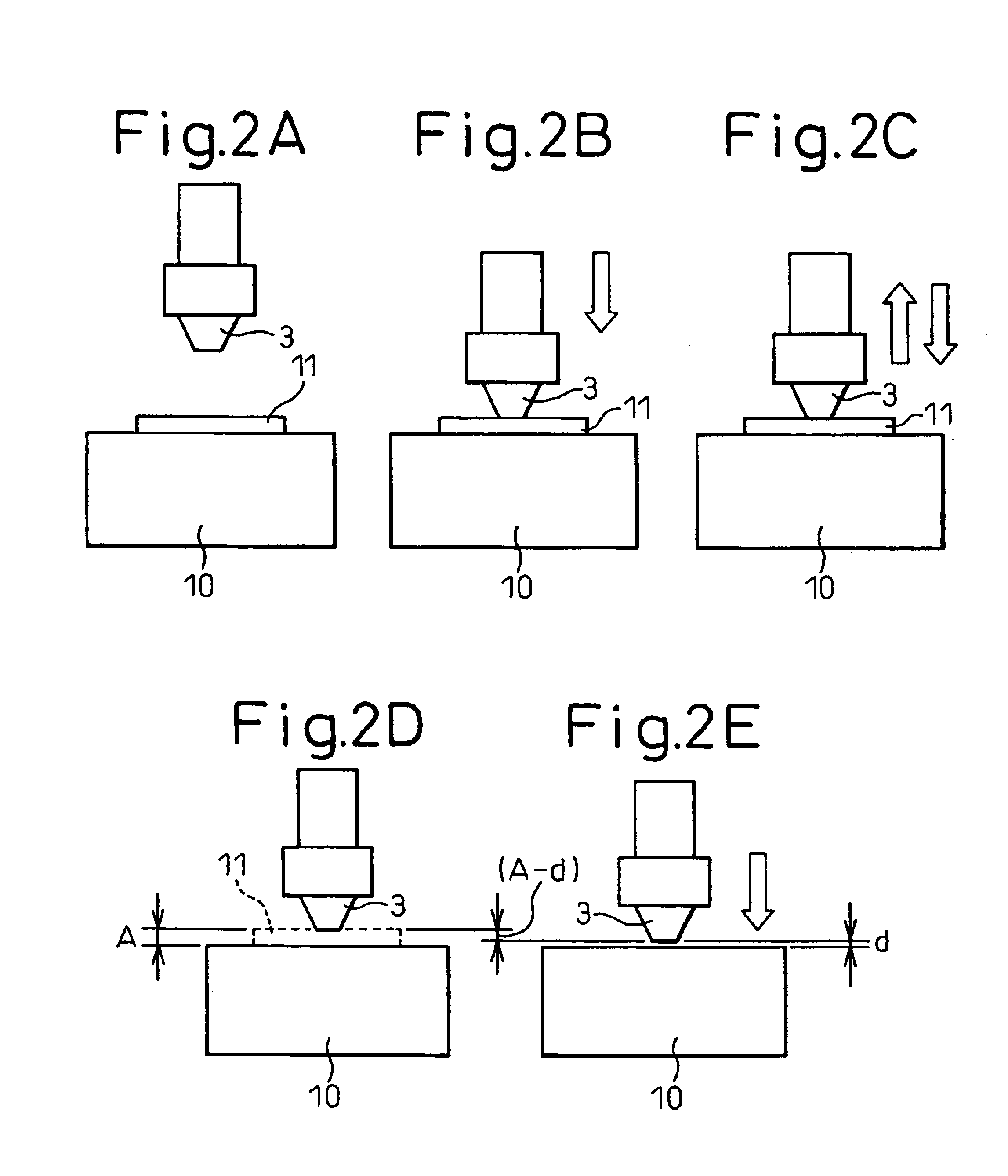
[0058]Next, as in steps S1 to S5 of the first embodiment, as shown in FIG. 4A, the upper nozzle 3 is moved to a position at a predetermined distance from the surface of the workpiece 10 by moving the support member 12 along the Z-axis, and the spacer member 11 of a known thickness A is placed between the upper nozzle 3 and the workpiece 10 (at step S12).

[0059]On the upper nozzle gap adjustment screen of the control unit 7, the upper nozzle gap adjustment mode is selected (at step S13), and the support member 12 is moved down along the Z-axis by activating the drive mechanism thereby to move the upper nozzle 3 toward the workpiece 10 (at step S14).

[0060]As shown in FIG. 4B, when the forward end of the upper nozzle 3 comes into contact with the surface of the spacer member 11, the generated torque of the Z-axis servo motor 6 reaches a predetermined value. The control unit 7 detects the contact by sensing this load torque, and outputs a contact detection signal when the sensed load tor...

third embodiment

[0067]FIGS. 6A to 6E and 7 are schematic diagrams and a flowchart, respectively, for explaining the steps of the method according to the In FIGS. 6A to 6E, only the upper nozzle 3, the workpiece 10 and the spacer member 11 are shown, while the remaining parts of the wire EDM 1 is omitted.

[0068]According to the third embodiment, the correction to compensate for the deformation of the drive mechanism, the workpiece 10, the upper nozzle 3, the spacer member 11, etc. due to the aforementioned contact between the forward end of the upper nozzle 3 and the spacer member 11 and / or for the displacement of the upper guide 4 caused by the pressure of the working fluid is made in the step of approximating the upper nozzle 3 into proximity with the spacer member 11.

[0069]In preparation for this correction, as in the steps S11 to S16 of the second embodiment, a deformation of the drive mechanism, the spacer member 11, the workpiece 10 and the upper nozzle 3 as well as a displacement of the upper...


PUM

PropertyMeasurementUnit
thicknessaaaaaaaaaa
distanceaaaaaaaaaa
gap distanceaaaaaaaaaa

Abstract

A method for adjusting the gap between an upper nozzle of a wire electric discharge machine includes placing a spacer member of a known thickness between a forward end of the upper nozzle and a workpiece. The forward end of the upper nozzle is brought into contact with the spacer member, so that the forward end of the upper nozzle is prevented from coming into direct contact with the workpiece. A Z-axis position of the upper nozzle is controlled on the basis of the thickness of the spacer member and the desired nozzle gap to set the gap between the forward end of the upper nozzle and the workpiece to a predetermined value. In controlling the Z-axis position of the upper nozzle, correction is made to compensate for a deformation of the upper guide, the spacer member, the workpiece, and the upper nozzle, and / or for a displacement of the upper guide resulting from a pressure of a working fluid.

Description

BACKGROUND OF THE INVENTION[0001]1. Field of the Invention[0002]The present invention relates to a nozzle gap adjusting method for setting a predetermined small gap, without contact, between a working fluid ejection nozzle and a workpiece in a wire electric discharge machine.[0003]2. Description of the Related Art[0004]In a wire electric discharge machine (wire EDM), a wire electrode is fed in an axial direction thereof while moving a workpiece and the wire electrode relatively to each other in a direction substantially perpendicular to the axial direction of the wire electrode. In the process, working fluid is ejected from a nozzle toward the machined portion, and intermittent voltage pulses (or voltage pulses constituting discharge pulses) are applied between the wire electrode and the workpiece so that the electric discharge is generated to machine the workpiece.[0005]In this wire EDM, the positioning and adjustment of the upper nozzle is performed to set a predetermined gap betw...

Claims


Application Information

Patent Timeline
Patent Type & Authority Patents(United States)
IPC IPC(8): B23H7/10B23H7/08B23H7/02
CPCB23H7/101
Inventor OKUDA, SHINJIISHIHARA, MITSUYOSHIKATO, JUNICHI
Owner FANUC LTD
Why Eureka
Try Eureka