Container with illuminated interior visual display

a technology of illuminated containers and visual displays, applied in the direction of lighting and heating apparatus, cleaning using liquids, instruments, etc., can solve the problems of creating visual interference, dilluminating the message or design of the inner container, and no prior art containers are known that use an inner container

Inactive Publication Date: 2005-08-02
HOY RICHARD DALE
View PDF112 Cites 78 Cited by
  • Summary
  • Abstract
  • Description
  • Claims
  • Application Information

AI Technical Summary

Benefits of technology

[0016]My invention is a container that provides aesthetically pleasing, unobstructed and effective illumination of a message or design on the outer surface of an inner container, the message or design being easily viewable through an outer container that supports the inner container.
[0017]A peripheral wall space, or cavity, is formed between the outer surface of the inner container and the outer container peripheral wall, the outer container being supported by a detachable base. A light source, in the form of at least one light emitting diode, is carefully positioned in the base near the perimeter of the attached outer container in order to introduce light directly from beneath the outer container, into the peripheral wall cavity and onto the inner container's outer surface. Positioning the light source near the perimeter of the outer container avoids undue illumination of the largely unviewable bottom of the inner container, which, in the case of a drinking vessel, should extend to, or near, the outer container bottom.
[0018]Placing the light source beneath the outer container and out of the peripheral space allows the peripheral space to be free of light source related hardware, such as wiring and diodes, that would otherwise obstruct the view of the illuminated message or design on the inner container.

Problems solved by technology

Although the above containers are useful, no prior art containers are known that use an inner container as the target area for illuminated messages and designs.
Such entrapment would dilute the illumination of the inner container message or design and possibly create visual interference.

Method used


Image

  • Container with illuminated interior visual display
  • Container with illuminated interior visual display
  • Container with illuminated interior visual display

Examples


Embodiment Construction

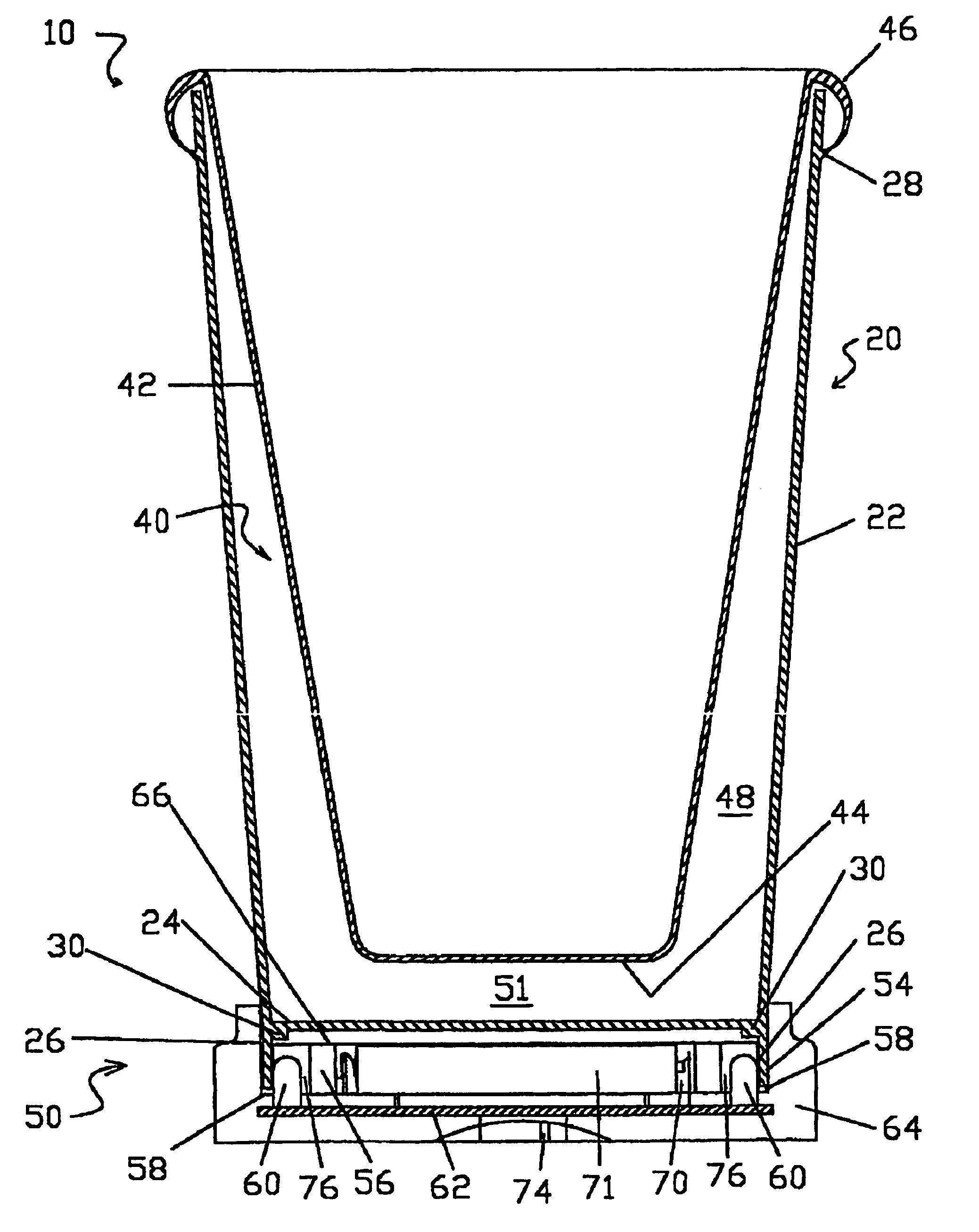
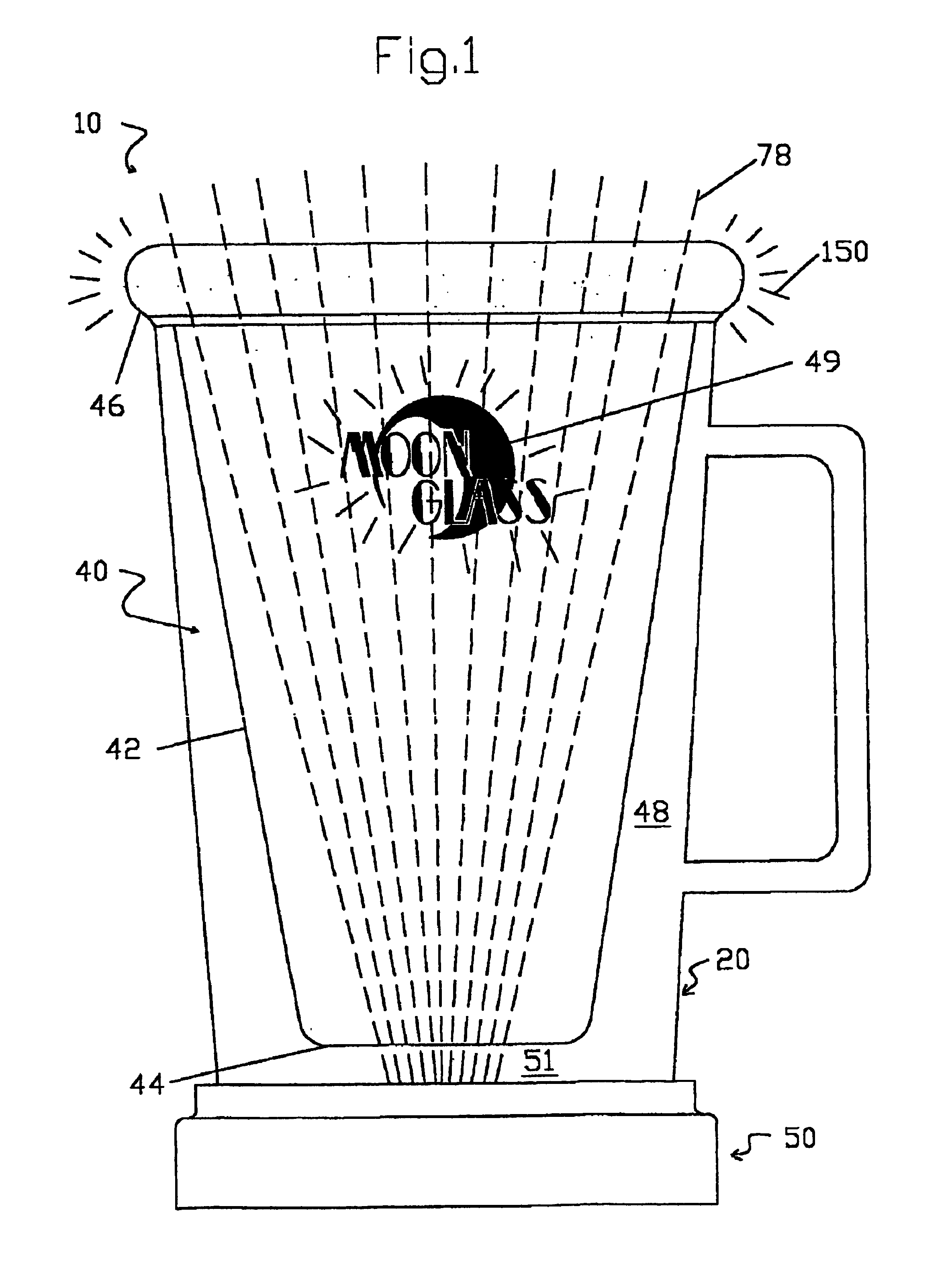
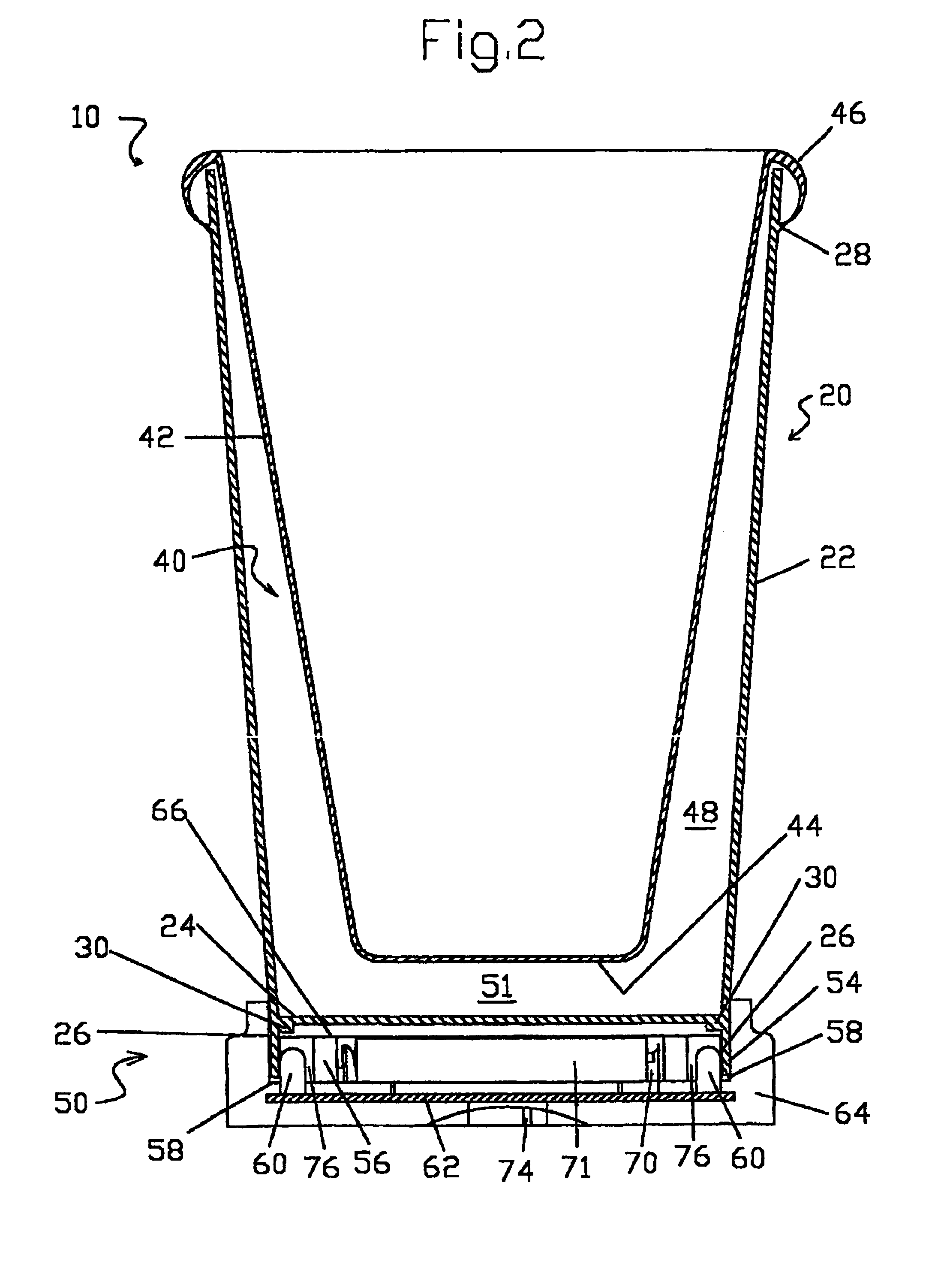
[0164]Turning now descriptively to the drawings, in which similar reference characters denote similar elements throughout the several views, FIGS. 1-15 illustrate the present invention indicated generally by the numeral 10.

[0165]A preferred embodiment of the container with illuminated interior visual display 10 is shown in FIGS. 1-3 and in a simplified exploded view in FIG. 5. The container 10 includes a transparent and circular outer container 20 having a peripheral wall 22 and a transparent bottom 24. Extending from the bottom 24 are feet 26. A shoulder 28 extends about the circumference of the outer container 22. An light altering element 30, in the form of an additional outer container bottom 24 thickness, is generally planar and extends downwardly from the outer container bottom 24, and is adjacent the outer container peripheral wall 22 about the outer container 20 circumference. A handle 32 is provided.

[0166]An inner container 40 has a peripheral wall 42, bottom 44, and upper ...


PUM


Abstract

An illuminated message or design is displayed on the surface of an inner container for viewing through an outer container. Light emitting diodes are placed under the outer container, and near its perimeter, allowing the light to be directly introduced into the peripheral wall cavity formed between the inner container and outer container. This allows optimal utilization of the light for lighting the inner container surface generally, and for directing a portion of the light to the inner container's bottom edge for entrapment within the inner container peripheral wall. The entrapped light is transmitted through the inner container peripheral wall until the light encounters a nonconformity that redirects the light outwardly through the outer container. Varying inner container shapes interact with the light and create several distinct light mantles.

Description

[0001]This is a 371 of PCT / US01 / 46040 filed Nov. 15, 2001 which is a cip of Ser. No. 09 / 716,544 filed Nov. 20, 2000 now U.S. Pat. No. 6,511,196.TECHNICAL FIELD[0002]The present invention relates generally to illuminated container displays. Such displays are highly desirable for advertising messages and other marketing efforts, and are particularly effective when illuminated and presented on such devices as mugs and tumblers.BACKGROUND ART[0003]Containers, including mugs and tumblers for beverages, are available in the industry and some include illumination and illuminated messages, designs, symbols, trademarks, patterns and the like.[0004]Among those containers is the wine glass disclosed in U.S. Pat. No. 3,735,113, issued to Thomas H. Stott for a fiber optical display in the wine glass. Light from a light source in the stem is confined within optical fibers and routed into a transparent double wall. The fibers create an optical display within the double wall at the ends of the fibe...

Claims


Application Information

Patent Timeline
Patent Type & Authority Patents(United States)
IPC IPC(8): A47G19/22G09F13/00G09F23/00
CPCA47G19/2227G09F13/00G09F23/00A47G2019/2238Y10S362/80Y10S362/806
Inventor HOY, RICHARD DALE
Owner HOY RICHARD DALE
Why Eureka
Try Eureka