Electrical apparatus intended for mounting on a subframe

Active Publication Date: 2005-08-02
SOCOMEC
View PDF10 Cites 5 Cited by
  • Summary
  • Abstract
  • Description
  • Claims
  • Application Information

AI Technical Summary

Benefits of technology

[0005]The present invention aims to remedy these problems by proposing an electrical apparatus in which each electrical terminal is arranged so that it can be connected laterally as well as towards the rear, which is simple to manufacture and use

Problems solved by technology

This enclosure can interfere with heat dissipation of these electrical apparatuses which then tend to overheat, resulting in accelerated aging.
In addition to this major disadvantage, it is necessary to stock all types of connecting tabs needed for all connection configurations, and to deliver the el

Method used


Image

  • Electrical apparatus intended for mounting on a subframe
  • Electrical apparatus intended for mounting on a subframe
  • Electrical apparatus intended for mounting on a subframe

Examples


Example

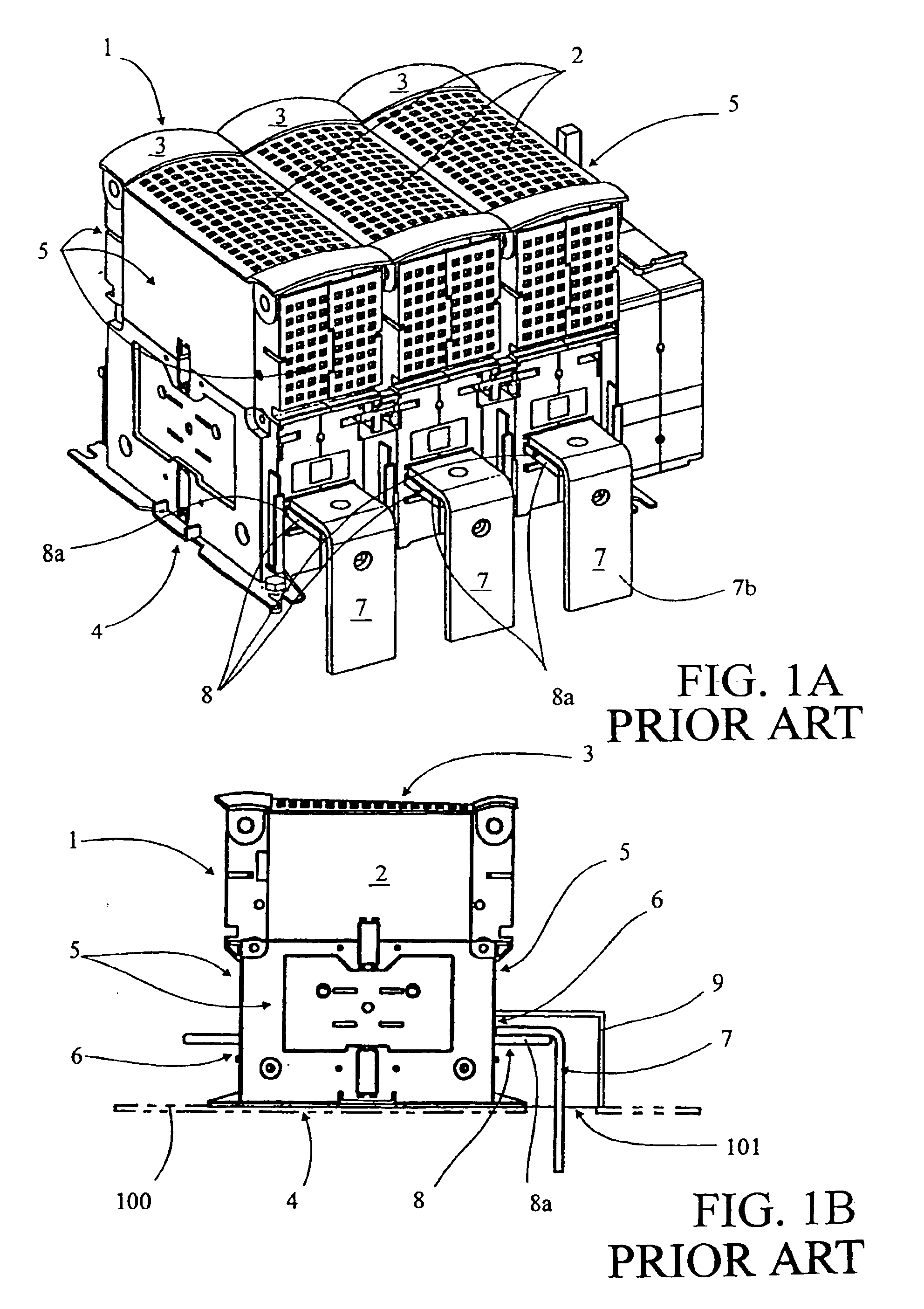
[0018]With reference to FIGS. 1A and 1B, known electrical apparatuses 1 are traditionally intended for mounting on frame 100, for example, a plate arranged in an electrical cabinet. These electrical apparatuses 1 have casing 2, which is, for example, parallelipipedic or any other suitable shape. This casing defines front wall 3 and rear wall 4 connected by four lateral walls 5, rear wall 4 being used for laying and attaching electrical apparatus 1 on frame 100. Electrical apparatus 1 has electrical terminals 8 housed in casing 2 and extending laterally beyond the casing through holes 6 whose dimensions are suited to those of electrical terminals 8.

[0019]Electrical connection of this electrical apparatus 1 is made directly on projecting parts 8a of electrical terminals 8. This electrical connection is generally lateral (left side of FIGS. 1A, 1B). In order to execute a rear connection, one uses L-shaped connecting tabs 7 that are mounted on projecting parts 8a of electrical terminals...


PUM


Abstract

An electrical apparatus for mounting on a frame that allows lateral connection as well as rear connection. The electrical apparatus (10) has connecting tabs (70, 70′) arranged for connection to the electrical terminals (80, 80′) of electrical apparatus (10) in such a way that they are removable and can be oriented in a lateral or rear position. The electrical terminals (80, 80′) have mounting zones (80a, 80′a) forming an angle α equal to 45° with a rear wall (40) of the casing (20), and the connecting tabs (70, 70′) have connecting segments (70b, 70′b) forming an angle β equal to 135° with the mounting segments (70a, 70′a). The casing (20) of the electrical apparatus (10) also has lateral openings (60, 60′) and rear openings (61, 61′) for the passage of connecting tabs (70, 70′) wherein the lateral (60, 60′) and rear (61, 61′) openings are closed by a cover (21).

Description

[0001]This application claims foreign priority under 35 U.S.C. §119 of French Patent Application FR 02 / 12307 filed Oct. 4, 2002.FIELD OF THE INVENTION[0002]The present invention relates to an electrical apparatus which is intended for mounting on a frame, this electrical apparatus having at least two electrical terminals housed in a casing.BACKGROUND OF THE INVENTION[0003]Such electrical apparatuses are generally used for single phase, three phase, or four phase low voltage electrical distribution, the current ranging from a few tens to several hundred A. These can be switches, fuse switches, changeover switches, circuit breakers or any other electrical apparatus.[0004]In a known manner, these electrical apparatuses are mounted in electrical distribution cabinets on plates or wiring frames. They are usually connected to an electrical circuit by electrical terminals that pass through the side walls of the casing and extend laterally beyond the casing. In certain configurations, howev...

Claims


Application Information

Patent Timeline
IPC IPC(8): H01R9/24
CPCH01R9/2416
Inventor DUMONT, ROGERROBERT, OLIVIER
Owner SOCOMEC
Why Eureka
Try Eureka