Method of making opacifying articles

Active Publication Date: 2020-03-19
EASTMAN KODAK CO
View PDF0 Cites 0 Cited by
  • Summary
  • Abstract
  • Description
  • Claims
  • Application Information

AI Technical Summary

Benefits of technology

[0077]In reference to a dry opacifying layer, the term “dry” means that the layer comprises water or auxiliary solvents (described below) in an amount of less than 5 weight %, or even less than 1 weight %, based on the total weight of the dry opacifying layer.
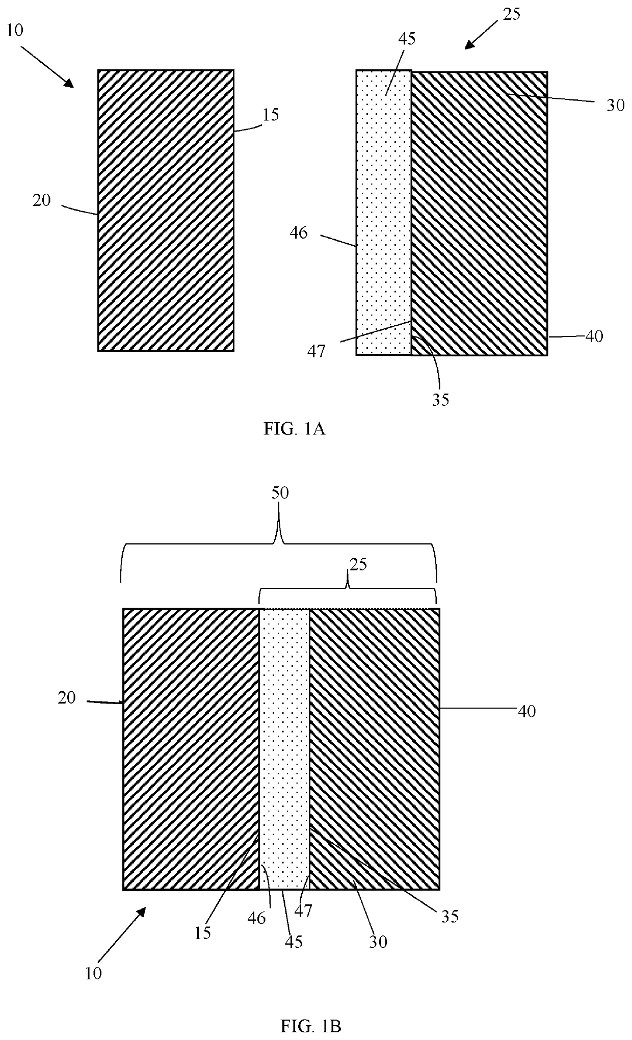
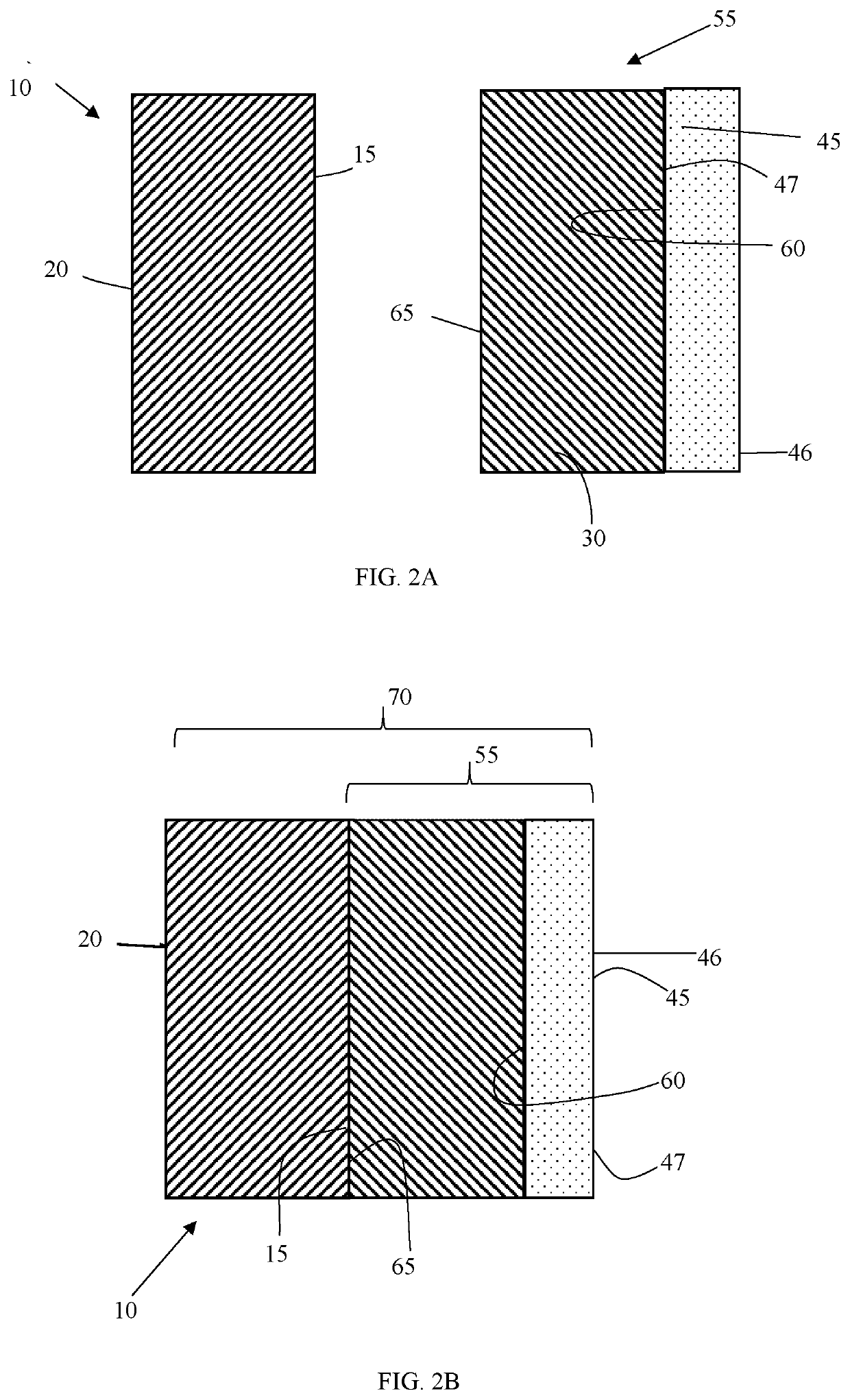
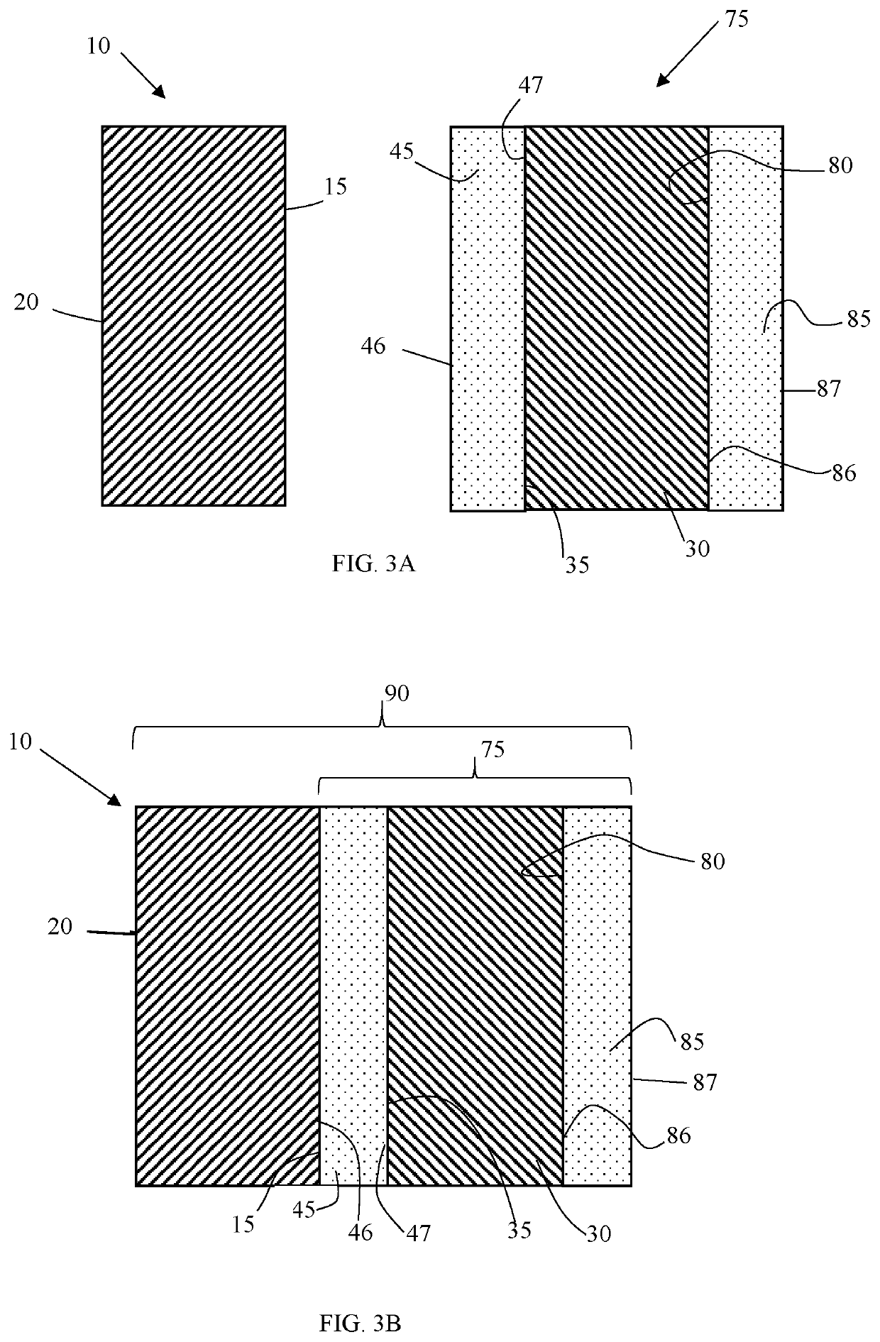
[0078]Each dry opacifying layer is generally disposed on an opposing surface of the substrate at a dry coverage of at least 50 g/m2 and up to and including 1000 g/m2, or of at least 100 g/m2 and up to and including 500 g/m2.
[0079]The opacifying element generally has a dry thickness of at least 100 μm or more likely of at least 300 μm, which dimension is intended to include the substrate, one or more dry opacifying layers, any intermediate adhesive layer, and any other materials adhered thereto. The average dry thickness can be determined by suitably measuring the opacifying element thickness, after drying, in at least three different places and taking an average of the measured values.
[0081]Porous particles used in the present invention containing discrete pores (or compartments or voids) are generally prepared using one or more water-in-oil emulsions in combination with an aqueous suspension process, such as in the Evaporative Limited Coalescence (ELC) process that is known in the art. The details for the preparation of the porous particles are provided, for example, in U.S. Pat. No. 8,110,628 (Nair et al.), U.S. Pat. No. 8,703,834 (Nair), U.S. Pat. No. 7,754,409 (Nair et al.), U.S. Pat. No. 7,887,984 (Nair et al.), U.S. Pat. No. 8,329,783 (Nair et al.), and U.S. Pat. No. 8,252,414 (Putnam et al.), the disclosures of all of which are incorporated herein by reference. Thus, the (a) porous particles are generally polymeric and organic in nature (that is, the continuous polymeric ph

Problems solved by technology

Thus, when a blackout material such as a blackout curtain or blackout shade is hung over a window, it generally blocks substantially all external light from entering the room through that window.
However, very thick foam coatings will be needed to create blackout curtains through which the sun is not visible in a darkened room using only these pigments.
When an electromagnetic radiation blocking coating has, as it often does, a strongly light absorbing material containing black pigments such as carbon black, between two reflective layers, it has at least two distinct problems.
First, such materials re

Method used


Image

  • Method of making opacifying articles
  • Method of making opacifying articles
  • Method of making opacifying articles

Examples


Example

Invention Examples 1a and 1b:

[0216]An aqueous composition was prepared by combining 19.4 weight % of NEOCRYL® A-6093 binder polymer, 0.9 weight % of TERGITOL® 15-S-7 surfactant, water, and 29.4 weight % of porous particles PX (having 0.1% carbon black in the discrete pores) in a container. The aqueous formulation was mixed with a Cowles blade until all porous particles were well dispersed, then de-gassed to remove large bubbles so there is no foam in this formulation. The resulting mixed aqueous composition was coated using a blade with a 0.024 inch (0.61 mm) gap onto a substrate (described above) and dried at 35° C. to form a dry opacifying layer on the laminate. The dry opacifying layer had a total dry coverage of 201 g / m2 (5.9 oz / yd2) and 0.06 weight % of carbon black. The resulting opacifying element laminate was laminated to the back side of a white woven fabric having a thickness of 0.0076 inches (0.02 cm) with the dry opacifying layer in contact with the fabric back side, to ...

Example

[0219]Invention Example 2 was prepared the same manner as Invention Example 1a except porous particles PY contained 0.05% of carbon black in the discrete pores were used. The aqueous composition was coated and dried in the same manner as for Invention Example 1a. The final dry opacifying layer in the opacifying element had a total dry coverage of 201 g / m2 and 0.03 weight % of carbon black. The opacifying element was laminated with the dry opacifying layer in contact with the back side of a white woven fabric to form an opacifying article (Invention Example 2a) according to the present invention.

[0220]A portion of this opacifying article was also flocked by applying an adhesive to the opposing surface of the opacifying element facing away from the fabric, followed by application of 0.1 mm cotton flock onto the adhesive with a hand-held sieve. The flocked surface had a fabric-like feel compared to a non-flocked sample of the same opacifying article.

Example

Invention Example 3:

[0221]Invention Example 3 was prepared in the same manner as Invention Example 1a except a 50 / 50 weight % mixture of porous particles PX and PY was used. The aqueous composition was coated and dried in the same manner as for Invention Example 1a. The dry opacifying layer contained a total dry coverage of 201 g / m2 and 0.04 weight % of carbon black. The resulting opacifying element was laminated to the back side of a white woven fabric with the dry opacifying layer in contact with the fabric back side.

[0222]The optical densities of the various opacifying articles and the colorimetric data of the opacifying elements are shown in TABLE I, wherein all the parameters are as described above. The data for the fabric alone is also shown in the following TABLE I.

TABLE IOpticalDensity(OD)L*a*b*YFabric only0.5484.02.6−10.764.1Invention7.177.82.2−5.152.8Example 1aInvention6.575.72.5−5.449.3Example 1bInvention4.183.52.2−5.963.1Example 2aInvention4.184.12.7−7.564.2Example 2b,Fl...


PUM

PropertyMeasurementUnit
Percent by massaaaaaaaaaa
Thicknessaaaaaaaaaa

Abstract

An opacifying article can be made using a (i) fabric having a face side and a back side and an (ii) opacifying element having a substrate that has first and second opposing surfaces; and a dry opacifying layer that has an inner surface and an outer surface. The dry opacifying layer is disposed with its inner surface in contact with the first opposing surface of the substrate. The dry opacifying layer has (a) 40-90 weight % of porous particles, each having a continuous polymeric phase and discrete pores dispersed within the continuous polymeric phase. The porous particles have a mode particle size of 2-50 μm and a porosity of 20-70 volume %. The dry opacifying layer also contains (b) 10-60 weight % of a binder material. The (ii) opacifying element is laminated to the back side of the fabric to provide the opacifying article.

Description

RELATED APPLICATION[0001]Reference is made to the following related application: U.S. Ser. No. 15 / ______ filed on even date herewith by Nair and Brick, entitled “Opacifying Articles” (Attorney Docket K002232 / JLT), the disclosure of which is incorporated herein by reference.FIELD OF THE INVENTION[0002]This invention relates to the field of light-blocking materials to provide shades, blinds, or other opacifying articles to block ambient light. In particular, this invention relates to methods for forming opacifying articles that are prepared by laminating an opacifying element containing porous particles to a fabric.BACKGROUND OF THE INVENTION[0003]In general, when light strikes a surface, some of it may be reflected, some absorbed, some scattered, and the rest transmitted. Reflection can be diffuse such as light reflecting off a rough surface like a white wall, in all directions, or specular, as in light reflecting off a mirror at a definite angle. An opaque substance transmits almost...

Claims


Application Information

Patent Timeline
IPC IPC(8): G02B5/00C08L1/14A47H23/10E06B9/24
CPCA47H23/10C08L2205/03C08L2205/14C08L1/14G02B5/003E06B9/24C08L2205/025A47H23/08Y10T156/10B32B37/12B32B37/182B32B2305/026B32B2305/18B32B2307/41
Inventor NAIR, MRIDULABRICK, MARY CHRISTINE
Owner EASTMAN KODAK CO
Why Eureka
Try Eureka