Method for depositing particles onto a substrate using an alternating electric field

a technology of alternating electric field and substrate, which is applied in the direction of aerosol delivery, nuclear engineering, microcapsules, etc., can solve the problems of limited amount of electrostatic deposition, preventing the reliable deposition of a controlled mass on the substrate, and electrostatic deposition technology. achieve the effect of high mass

Inactive Publication Date: 2005-08-02
MICRODOSE THERAPEUTX INC
View PDF117 Cites 78 Cited by
  • Summary
  • Abstract
  • Description
  • Claims
  • Application Information

AI Technical Summary

Benefits of technology

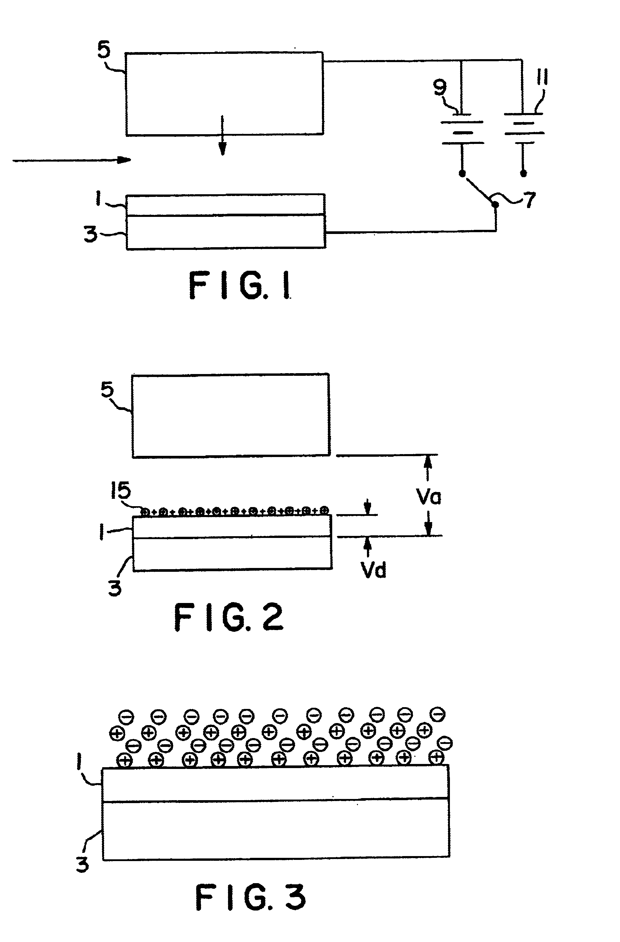
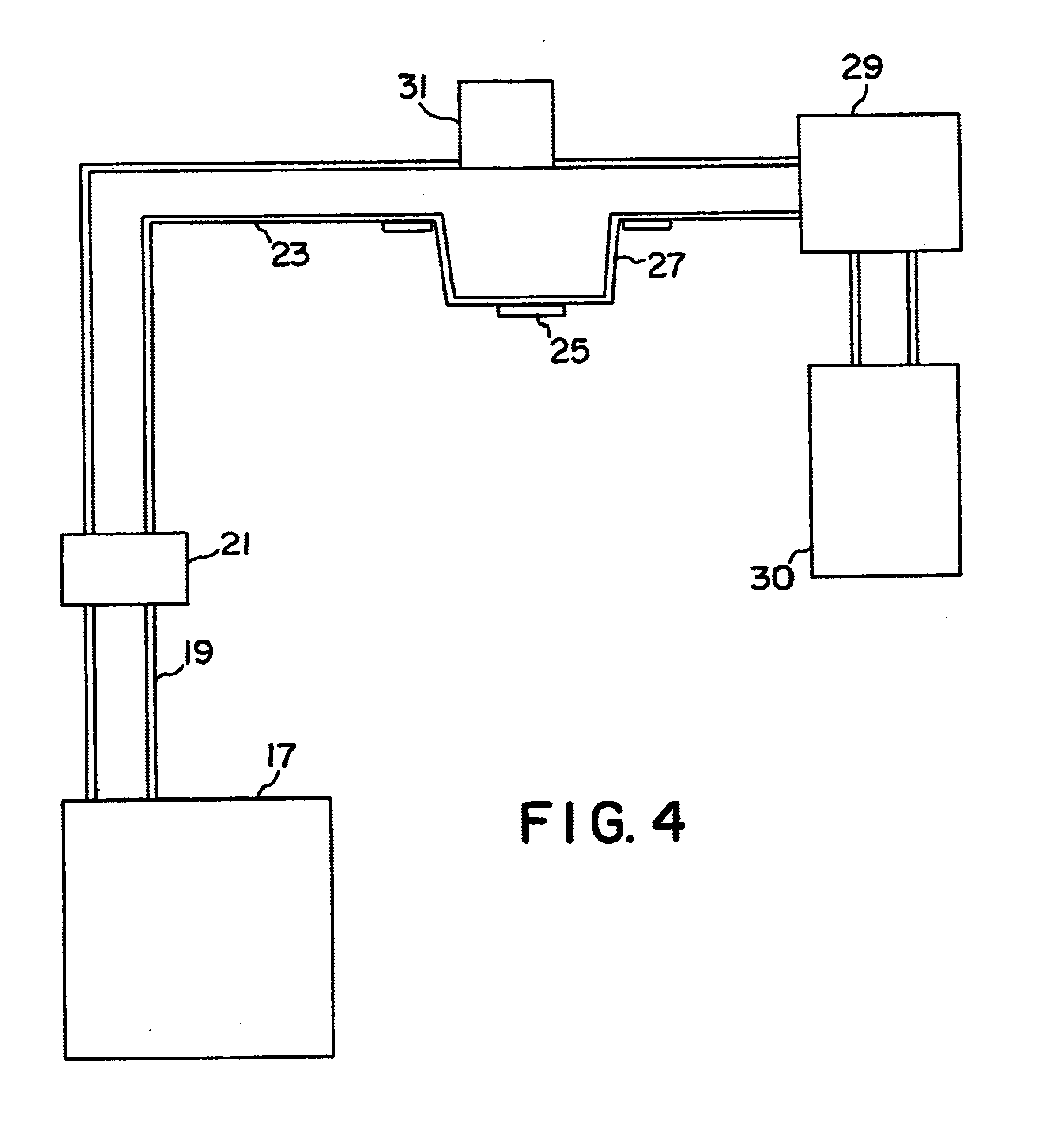
[0005]The above disadvantages are overcome in the present invention by providing an alternating electric field for depositing particles onto a dielectric substrate. More particularly, the present invention comprises a method and apparatus for depositing particles from an aerosol onto a dielectric substrate wherein the method comprises and the apparatus embodies the following steps: charging the aerosol particles, positioning them in a deposition zone proximate to the dielectric, and applying an alternating field to the deposition zone by which the aerosol particles are removed from the aerosol and deposited on the dielectric substrate thus forming a deposit. The alternating field provides the means to deposit charged particles and / or ions such that the accumulation of charge on the dielectric substrate does not prevent further deposition of particles thus enabling electrostatic deposition of a deposit with relatively high mass.
[0006]In one embodiment of the invention, the particles are alternately charged in opposite polarities and deposited on the substrate with the alternating electric field, thus preventing charge accumulation on the dielectric substrate.

Problems solved by technology

While electrostatic deposition has been proposed for packaging powdered drugs (see U.S. Pat. Nos. 5,669,973 and 5,714,007 to Pletcher), electrostatic deposition is limited by the amount of mass that can be deposited in a given area.
This limitation is intrinsic to electrostatic deposition technology and is determined by the combination of the amount of charge that can be placed on the photoreceptor and the charge to mass ratio of the toner particles.
This variation prevents the reliable deposition of a controlled mass on the substrate.
Furthermore, low charge to mass ratio particles limit the overall speed of deposition because the force of a particle, which sets the particle velocity, from an electrostatic field is proportional to the charge carried by the particle.
This approach is subject to limitations in mixing uniformity and the aspiration of extraneous matter.
However, from this discussion it is apparent, aside from the disadvantages, that dry powder particles may also be used.
However, an apparatus for depositing powder on a dielectric (i.e. a powder carrying package) using the Pressman approach also suffers from the above described maximum amount of powder that can be deposited on the dielectric.

Method used


Image

  • Method for depositing particles onto a substrate using an alternating electric field
  • Method for depositing particles onto a substrate using an alternating electric field
  • Method for depositing particles onto a substrate using an alternating electric field

Examples


example

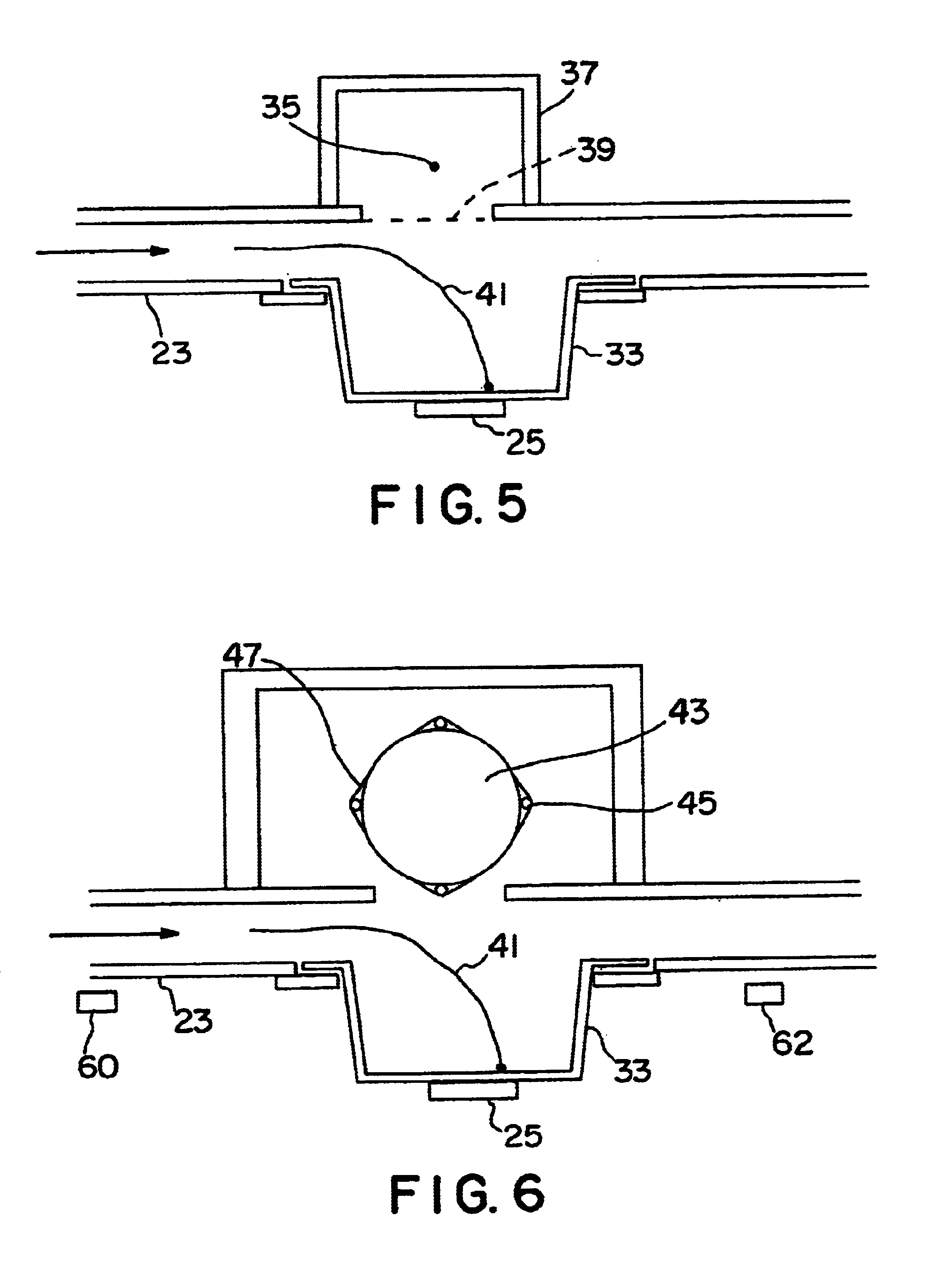
[0036]A filling device was set up according to the schematic of FIG. 6. The channel was fabricated of ¼-inch thick polycarbonate sheet. The channel width was 40-mm and its height was 6-mm. A blister pack pocket, formed of 6-mil polyvinyl chloride, having a depth of 4-mm and a diameter of 6-mm was supported on a circular electrode 25 having a diameter of 4-mm.

[0037]The charge source, consisting of glass core rod 43, spiral wire electrode 47 and four glass coated wire 45 spaced at intervals around the periphery of the core rod, was obtained from Delphax Systems, Canton, Mass. Delphax customers employ these rods in discharging (erasing) latent images on Delphax high-speed printer drums.

[0038]Spiral winding 47 was maintained at ground potential and glass coated tungsten wire 45 was excited using 2300 volt peak-to-peak ac at a frequency of 120 kHz. A Trek high voltage amplifier was employed to provide square wave switching of deposition electrode 25 at a frequency of 35 Hertz. The output...


PUM

PropertyMeasurementUnit
electric fieldaaaaaaaaaa
frequencyaaaaaaaaaa

Abstract

Uniform portions of fine powders are deposited on a substrate by electrostatic attraction in which the charge of the electric field and polarity of the charged particles are varied repeatedly to form a buildup of powder on the carrier surface.

Description

BACKGROUND OF THE INVENTION[0001]This invention is directed towards the deposition of small (usually fractional gram) masses on a generally electrically non-conductive substrate. One of the most common methods for accomplishing the goal is practiced by manufacturers of photocopiers and electrophotographic electronic printers. This involves causing charged toner particles to migrate with an electric field to a charged area on a photoreceptor, so-called electrostatic deposition. While electrostatic deposition has been proposed for packaging powdered drugs (see U.S. Pat. Nos. 5,669,973 and 5,714,007 to Pletcher), electrostatic deposition is limited by the amount of mass that can be deposited in a given area.[0002]This limitation is intrinsic to electrostatic deposition technology and is determined by the combination of the amount of charge that can be placed on the photoreceptor and the charge to mass ratio of the toner particles. The mass that can be deposited in an area of a substrat...

Claims


Application Information

Patent Timeline
Patent Type & Authority Patents(United States)
IPC IPC(8): B05B5/08B05B5/00B05D1/06
CPCB05B5/007B05B5/008B05B5/087B05D1/06
Inventor FOTLAND, RICHARDBOWERS, JOHNJAMESON, WILLIAM
Owner MICRODOSE THERAPEUTX INC
Why Eureka
Try Eureka