Method of reactive power regulation and aparatus for producing electrical energy in an electrical network

a technology of reactive power regulation and electrical network, applied in the direction of reactive power adjustment/elimination/compensation, ac network to reduce harmonics/ripples, electric variable regulation, etc., can solve the problem of negative effect on the stability of the electrical network, inability to complete compensation of inductive reactive power through phase-shifting capacitors, etc. problem, to achieve the effect of easy adjustment or regulation

Inactive Publication Date: 2005-08-02
WOBBEN ALOYS
View PDF70 Cites 44 Cited by
  • Summary
  • Abstract
  • Description
  • Claims
  • Application Information

AI Technical Summary

Benefits of technology

[0006]In this respect, by means of the regulation in accordance with the invention, it is preferably also possible for the electrical power produced to be of a frequency which corresponds to the frequency of the consumer or also represents a multiple of the consumer frequency. In the former case accordingly reactive power can be supplied at the frequency of the consumer or the network frequency of the electrical network. In the latter case for example as desired harmonic reactive power can be fed into the electrical network. For example the fifth harmonic can be fed into the network, at a frequency of 250 Hz, as a capacitive harmonic. That then compensates for the harmonic reactive power of electrical consumers which are connected to the electrical network such as for example televisions, energy-saving lamps and so forth.
[0007]Desirably the compensation device has an inverter with which phase, amplitude and/or frequency of the voltage and/or current characteristics can be particularly easily adjusted or regulated in order to produce a reactive power component which is suitable for appropriately compensating for the reactive power in the consumer.
[0008]Preferably the compensation device has a mea

Problems solved by technology

Complete compensation of the inductive reactive power by means of phase-shifting capacitors is however not possible in practice precisely when high power fluctuations are involved.
A further disadvantage is that the phase-shiftin

Method used


Image

  • Method of reactive power regulation and aparatus for producing electrical energy in an electrical network
  • Method of reactive power regulation and aparatus for producing electrical energy in an electrical network
  • Method of reactive power regulation and aparatus for producing electrical energy in an electrical network

Examples


Embodiment Construction

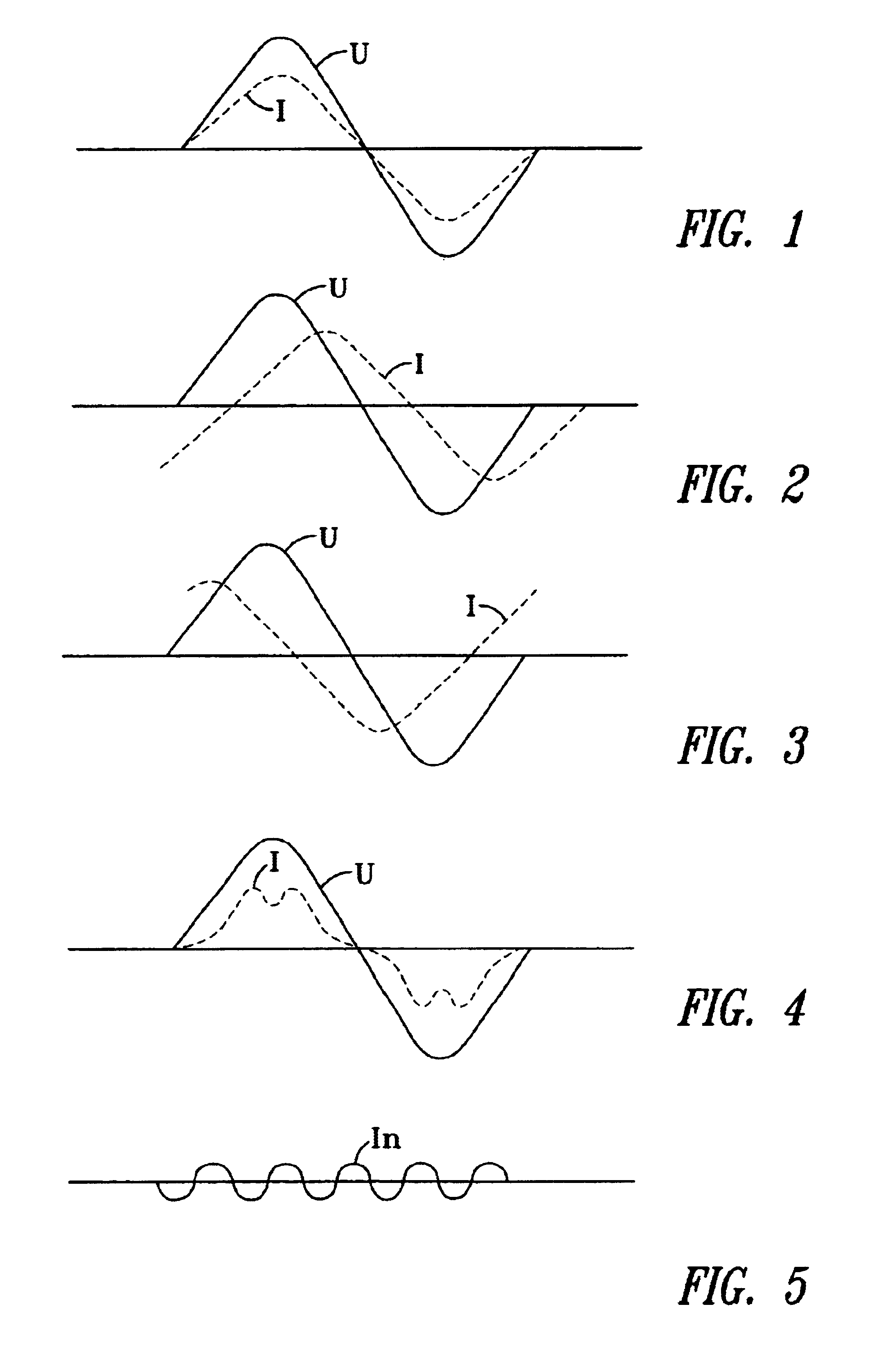
[0018]The occurrence of fundamental oscillation reactive powers in an electrical network has already long been known. FIGS. 1 to 3 show various voltage and current configurations.

[0019]FIG. 1 shows a situation in which there is no reactive power, that is to say voltage U and current 1 are not phase-shifted. The current neither leads nor trails the voltage. There is therefore no fundamental oscillation reactive power.

[0020]FIG. 2 shows the situation in which the current I trails the voltage U in respect of time. In this respect, inductive reactive power is required, which is the case with most electrical consumers as they—such as for example electric motors have inductors.

[0021]FIG. 3 shows the situation in which the current I leads the voltage U in respect of time. Capacitive reactive power is required in this case.

[0022]FIG. 4 shows an oscillation in the reactive power. FIG. 5 shows the harmonic component from the current configuration of FIG. 4.

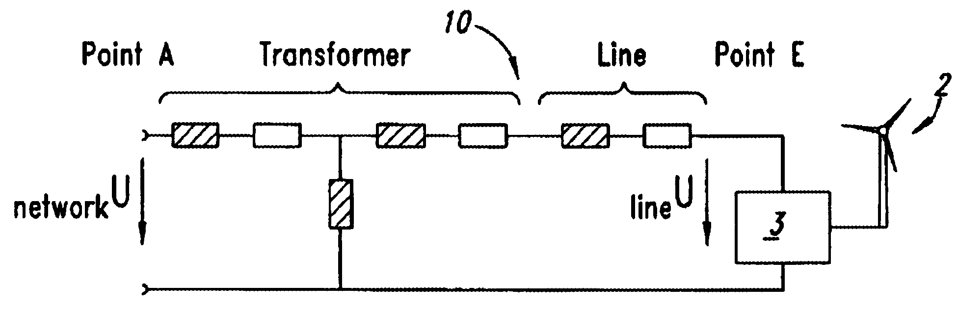
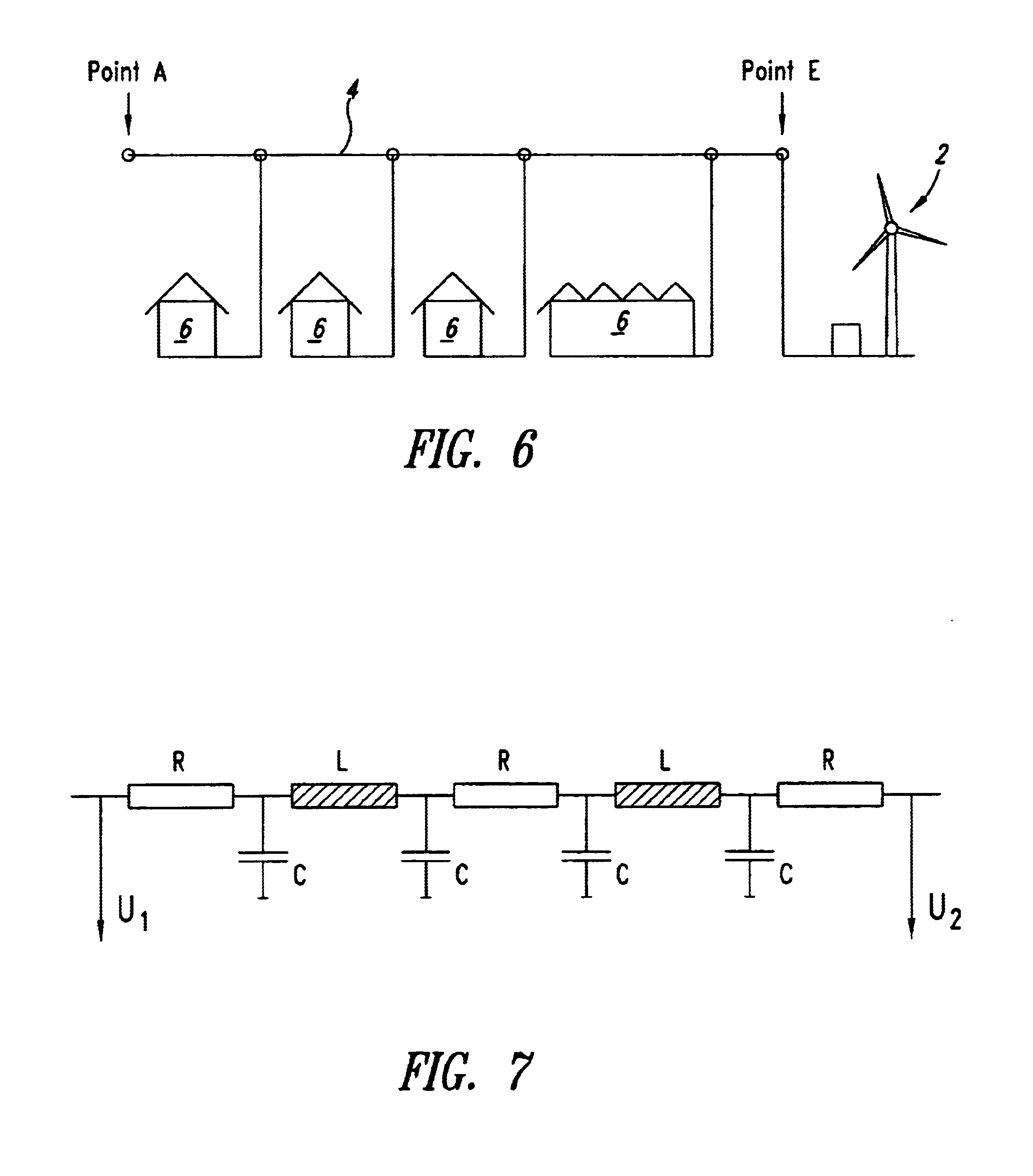
[0023]FIG. 6 shows an arrangement in...


PUM


Abstract

A method of reactive power regulation in an electrical network in which electrical power is produced by an electrical generator preferably driven by the rotor of a wind power installation and suitably modulated by means of a compensation device between the generator and the network for the compensation of reactive power, and an apparatus for producing electrical energy in an electrical network, preferably an electrical generator driven by the rotor of a wind power installation and a compensation device between the generator and the network for the compensation of reactive power. The compensation device is so regulated that the electrical power delivered to the consumer has a reactive power component which is adapted in respect of its phase, amplitude and/or frequency to the consumer in such a way as to compensate for the reactive power in the consumer.

Description

TECHNICAL FIELD[0001]The invention concerns a method of reactive power regulation in an electrical network, in which electrical power is produced by an electrical generator preferably driven by the rotor of a wind power installation and suitably modulated by means of a compensation device between the generator and the network for the compensation of reactive power. The invention further concerns an apparatus for producing electrical energy in an electrical network, comprising an electrical generator preferably driven by the rotor of a wind power installation and a compensation device between the generator and the network for the compensation of reactive power.BACKGROUND OF THE INVENTION[0002]Many consumers connected to the electrical network require inductive reactive power. Compensation of such an inductive reactive power component is effected by using capacitors which are also referred to as phase-shifting capacitors whose capacitive reactance is approximately as high as the induc...

Claims


Application Information

Patent Timeline
IPC IPC(8): H02J3/18H02J3/01H02J3/16H02J3/50
CPCH02J3/01H02J3/1842Y02E10/763Y02E40/22Y02E40/40Y02E10/76Y02E40/20
Inventor WOBBEN, ALOYS
Owner WOBBEN ALOYS
Why Eureka
Try Eureka