Clutter rejection in a passive radar receiver of OFDM signals

a passive radar and receiver technology, applied in direction finders using radio waves, instruments, reradiation, etc., can solve the problems of not optimizing methods, becoming impossible to detect targets, and difficult, if not impossible, to achieve the theoretically achievable detection performance limits of mobile targets

Inactive Publication Date: 2005-08-02
OFFICE NAT DETUD & DE RECH AEROSPATIALES
View PDF10 Cites 35 Cited by
  • Summary
  • Abstract
  • Description
  • Claims
  • Application Information

AI Technical Summary

Benefits of technology

[0020]The second embodiment provides also a means for estimating an emitted signal replica as a function of the spectral lines of one of the symbols signals by estimating coefficients of t

Problems solved by technology

In the radar field, it is generally difficult, if not impossible, to achieve the theoretically achievable detection performance limits for a mobile target.
This is because detection performances are conditioned by the signal to thermal noise ratio at the output of a tuned filter in the radar receiver and in practise is generally limited not by thermal noise but by clutter at the output of the tuned filter.
Consequently, these methods are not optimized in the context of the fight against clutter when the latter is rich

Method used


Image

  • Clutter rejection in a passive radar receiver of OFDM signals
  • Clutter rejection in a passive radar receiver of OFDM signals
  • Clutter rejection in a passive radar receiver of OFDM signals

Examples


first embodiment

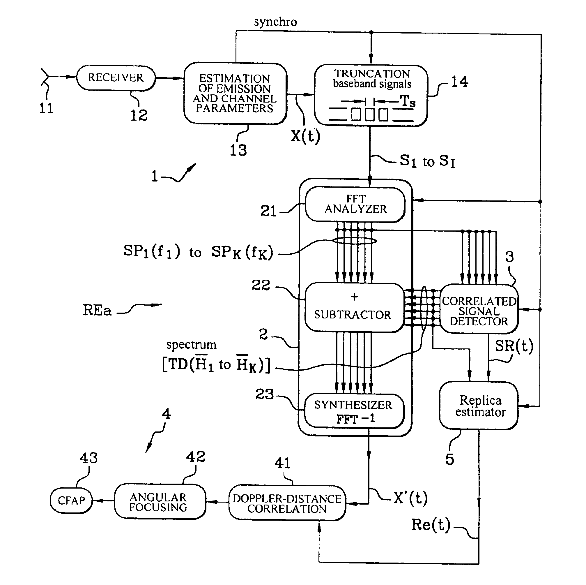
[0062]Although this first embodiment has been described for a bistatic radar, it can be applied to a monostatic radar. It can also be used in a radar with a plurality of receive antennas and therefore a plurality of filtering operations by subtracting spectral lines depending on transfer function coefficients {overscore (H)}1 to {overscore (H)}K for the K spectral lines relating to each receive antenna in the filtering circuit 2, which produces as many filtered signals X′(t) as there are antennas to be processed in parallel in the Doppler channels of the circuit 4, as in the circuit 4b shown in FIG. 6.

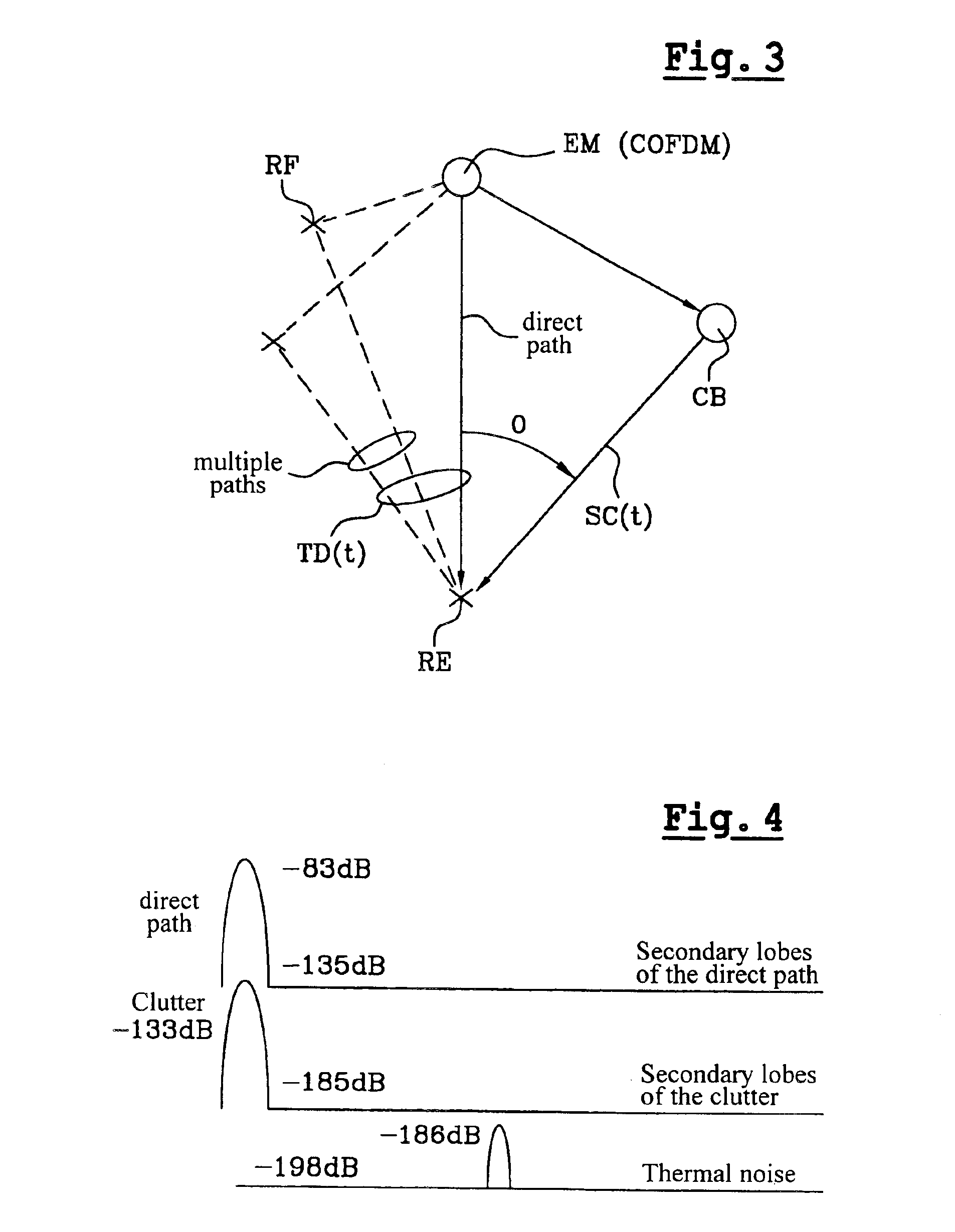
[0063]In the embodiment described above with reference to FIG. 5, the received signal X(t) is processed to eliminate the contribution of the direct path and the multiple paths between at least one COFDM emitter EM and the receiver REa. However, scatterers, such as interference and thermal noise in the wanted frequency band, are not eliminated in the signal X′(t) processed by the correl...

second embodiment

[0064]In a second embodiment, shown in FIG. 6, the radar receiver REb aims to eliminate all correlated unwanted signals and scatterers.

[0065]The receiver REb for COFDM signals comprises a plurality of receiver antennas 111 to 11N connected to a plurality of receivers 121 to 12N, respectively, with N≧2. The radar receiver REb has a structure identical to that of the receiver REa shown in FIG. 5, but with N parallel receive channels between the circuits 13b, 14b, 2b and 4b respectively associated with the antennas 111 to 11N.

[0066]The detector 3 and the replica estimator 5 are not modified. The detector 3 produces the reference signal SR(t) relating to one of the antennas 111 to 11N, for example as a function of the K spectral lines SP11 to SPK1 of the first channel connected to the antenna 111, which are delivered by the spectrum analyzer 21b which analyzes N received symbol streams supplied by the truncator circuit 14b. The estimator 5 produces a narrowband emitted signal replica Re...


PUM


Abstract

The invention concerns a passive radar receiver for a received orthogonal frequency division multiplex-type signal consisting of symbol frames each emitted on coded orthogonal carriers. After formatting the received signals into digital symbols (S1 S1), a filtering circuit (2) eliminates by subtraction or using a covariance matrix, in the symbol signal at least unwanted signals with null Doppler effect so as to apply a filtered signal (X′) including essentially signals backscattered by mobile targets to a Doppler-distance correlator (4).

Description

CROSS-REFERENCE TO RELATED APPLICATIONS[0001]This application is a national phase of the PCT International Application No. PCT / FR02 / 00224 filed Jan. 18, 2002, which is based on the French Application No. 01-01695 filed Feb. 07, 2001.BACKGROUND OF THE INVENTION[0002]1. Field of the Invention[0003]The present invention relates to a passive radar receiver receiving a radio signal comprising frames of symbols each emitted on orthogonal coded carriers.[0004]2. Description of Related Art[0005]In the radar field, it is generally difficult, if not impossible, to achieve the theoretically achievable detection performance limits for a mobile target. This is because detection performances are conditioned by the signal to thermal noise ratio at the output of a tuned filter in the radar receiver and in practise is generally limited not by thermal noise but by clutter at the output of the tuned filter. In the present context the term clutter is to be interpreted in the wide sense of all paths wit...

Claims


Application Information

Patent Timeline
IPC IPC(8): G01S13/00G01S13/524G01S7/02G01S7/41G01S7/292H04J11/00
CPCG01S7/414G01S13/003G01S13/524
Inventor POULLIN, DOMINIQUE
Owner OFFICE NAT DETUD & DE RECH AEROSPATIALES
Why Eureka
Try Eureka