Heat dissipation assembly including heat sink and fan

a technology of heat dissipation assembly and fan, which is applied in the direction of electrical apparatus construction details, basic electric elements, lighting and heating apparatus, etc., can solve the problems of large heat generation, abnormal operation or damage, unduly laborious and slow locking by this means, and achieve convenient and safe assembly

Inactive Publication Date: 2005-08-02
HON HAI PRECISION IND CO LTD
View PDF17 Cites 22 Cited by
  • Summary
  • Abstract
  • Description
  • Claims
  • Application Information

AI Technical Summary

Benefits of technology

[0007]Accordingly, an object of the present invention is to provide a heat dissipation assembly including a heat sink and a fan, and which can be conveniently and safely assembled.

Problems solved by technology

Numerous modem electronic devices such as central processing units (CPUs) of computers operate at high speed and thus generate large amounts of heat.
The heat must be efficiently removed from the CPU; otherwise, abnormal operation or damage may result.
Most commonly, a fan is locked onto a heat sink by screws interferentially engaged with fins of the heat sink.
Locking by this means is unduly laborious and slow.
Additionally, the fins of the heat sink are generally thin and are liable to be deflected.
Thus, the screws may loosen from the fins.
The fan is liable to operate less efficiently, and may even become unserviceable.
However, screws are still needed.
Locking the fan to the fan holder by this means is still laborious and slow.
Furthermore, the combined fan and fan holder are placed on the heat sink without any adequate positioning element.
The combination is liable to be displaced before the clips are engaged with the retention frame.
This may lead to faulty engagement of the clips with the retention frame.

Method used


Image

  • Heat dissipation assembly including heat sink and fan
  • Heat dissipation assembly including heat sink and fan
  • Heat dissipation assembly including heat sink and fan

Examples


Embodiment Construction

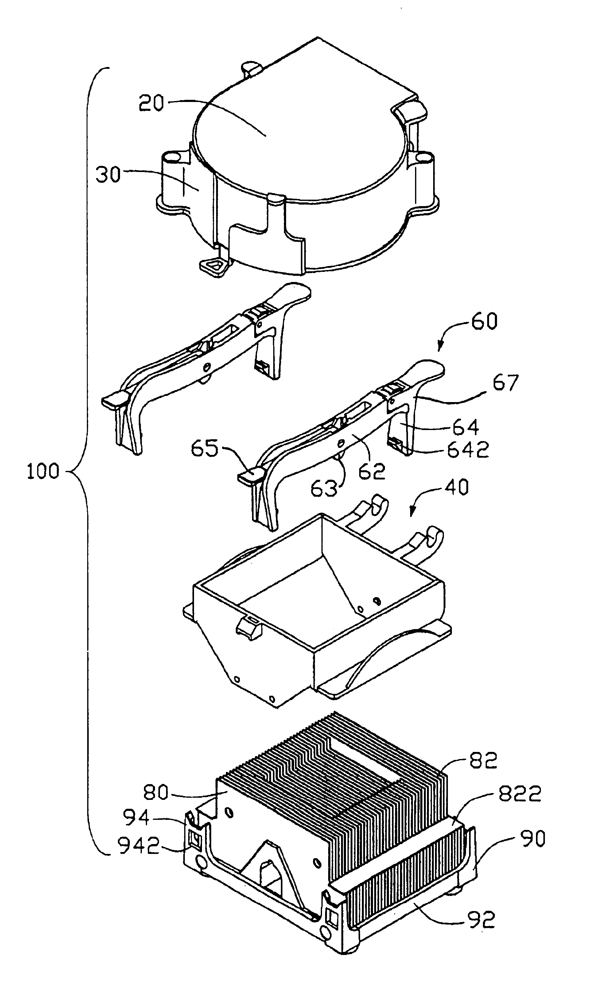
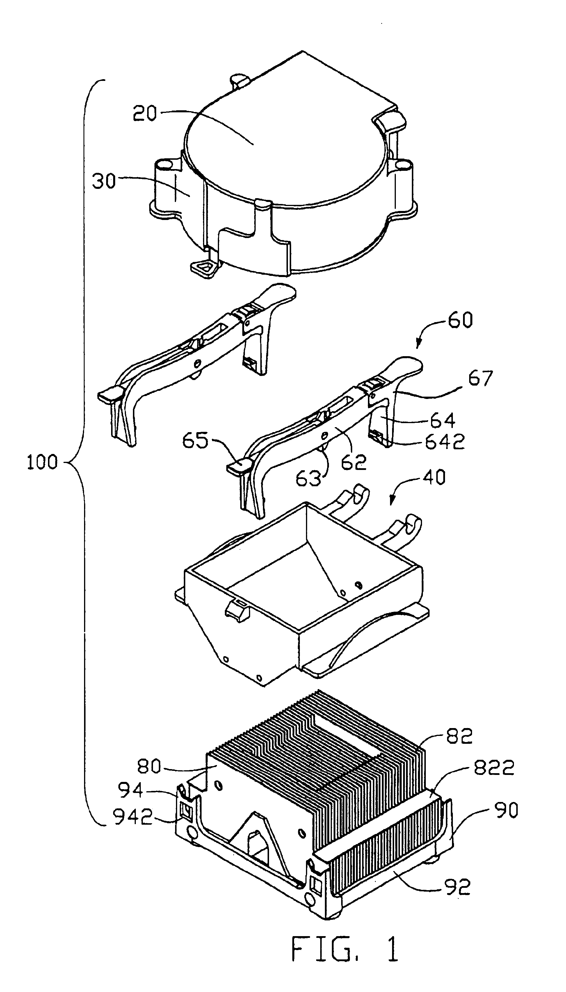
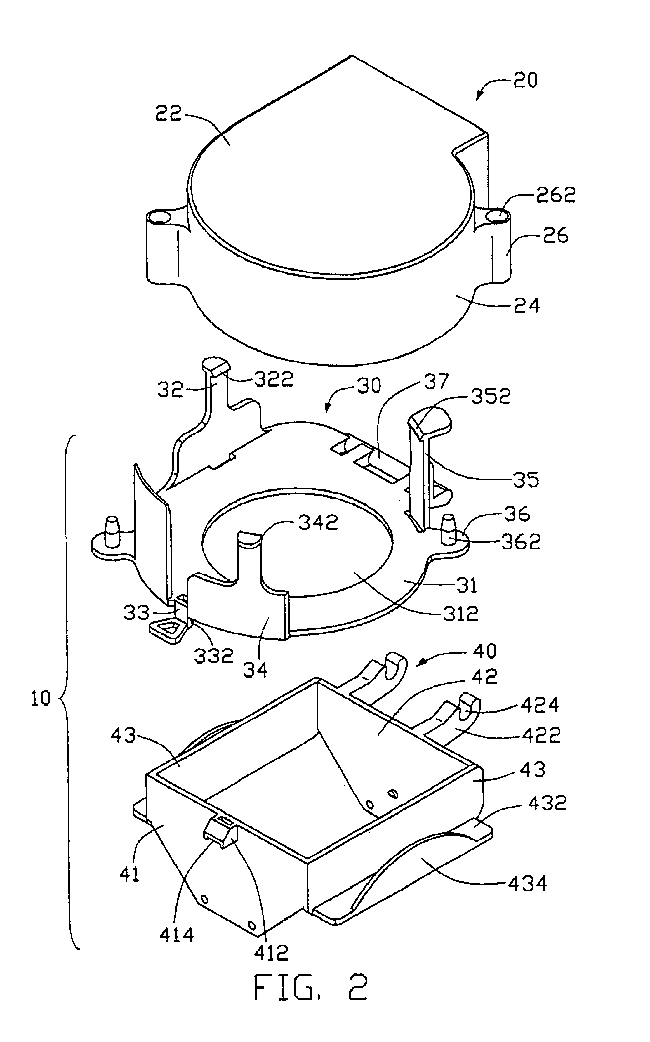
[0015]Referring to FIGS. 1-5, a heat dissipation assembly 100 in accordance with the preferred embodiment of the present invention comprises a fan holder 10, a fan 20, a pair of clips 60, a heat sink 80 and a retention frame 90. The fan holder 10 holds the fan 20, and is mounted on the heat sink 80. The retention frame 90 supports the heat sink 80 thereon. The clips 60 are mounted on the fan holder 10, and are engaged with the retention frame 90.

[0016]The heat sink 80 comprises a plurality of parallel fins 82. A pair of recessed shoulders 822 is formed at opposite sides of the fins 82 respectively. Each clip 60 is substantially “n” shaped, and comprises a horizontal beam 62 and a pair of clamping legs 64 extending from opposite ends of the beam 62 respectively. Each clamping leg 64 forms an inward hook 642 at a free end thereof. Structurally, each clip 60 includes an actuator arm 65 pivotally mounted to the beam 62 and having a cam 63 thereof around the pivot region to decide the te...


PUM


Abstract

A heat dissipation assembly (100) includes a retention frame (90), a heat sink (80), a fan holder (10), a pair of clips (60) and a fan (20). The heat sink is mounted on the retention frame and forms a pair of shoulders (822) at opposite sides thereof. The fan holder includes a fan duct (40) surrounding a top portion of the heat sink and including a pair of supports mounted on the shoulders, and a holding frame (30) detachably mounted on the fan duct. The clips are mounted on the supports and engaged with the retention frame. One side of the holding frame is pivotally engaged with the fan duct, an opposite side of the holding frame forms a latching leg (33) that is engaged with an ear (412) formed at the fan duct. Three catching arms extend from the holding frame and retain the fan in the holding frame.

Description

BACKGROUND OF THE INVENTION[0001]1. Field of the Invention[0002]The present invention relates to a heat dissipation assembly having a heat sink and a fan, and more particularly to a heat dissipation assembly having a fan holder that comprises a first part mounted on the heat sink and a second part retaining the fan therein.[0003]2. Description of Prior Art[0004]Electronics technology continues to boom unabated. Numerous modem electronic devices such as central processing units (CPUs) of computers operate at high speed and thus generate large amounts of heat. The heat must be efficiently removed from the CPU; otherwise, abnormal operation or damage may result. Typically, a heat sink with good thermal conducting capability is mounted onto the CPU, and a fan is mounted onto the heat sink to enhance the heat dissipation capability thereof.[0005]Most commonly, a fan is locked onto a heat sink by screws interferentially engaged with fins of the heat sink. Locking by this means is unduly l...

Claims


Application Information

Patent Timeline
Patent Type & Authority Patents(United States)
IPC IPC(8): H01L23/467H01L23/40H01L23/34
CPCH01L23/4093H01L23/467H01L2924/0002H01L2924/00
Inventor CHEN, CHUN-CHILAN, CHIN HSIENFU, MENG
Owner HON HAI PRECISION IND CO LTD
Why Eureka
Try Eureka