
Broadcast receiver and channel scanning method

Active Publication Date: 2005-08-02
ALPINE ELECTRONICS INC
View PDF7 Cites 5 Cited by
  • Summary
  • Abstract
  • Description
  • Claims
  • Application Information

AI Technical Summary

Benefits of technology

[0008]The present invention has been accomplished in view of the above-mentioned technical background, and it is an object of the present invention to realize an improvement which enables a user to identify broadcast contents of a channel being currently received with accuracy, even though the broadcast contents may change during a scanning time period.
[0009]It is another object of the present invention to realize an improvement which controls a receive channel such that the broadcast contents of the receive channel do not change within a scanning time period, thereby enabling a user to identify the broadcast contents with certainty.
[0010]To solve the foregoing problems, according to a first aspect of the present invention, there is provided a channel scanning method in a multi-channel broadcast for switching a receive channel at predetermined time intervals, comprising: checking whether or not the broadcast contents of a receive channel being currently received, after the channel switching, change within the predetermined time interval; and prolonging a time period for receiving the channel, which is being received, in a case where the broadcast contents change. Thus, even if the broadcast contents change, the scanning time period is prolonged, thereby allowing the user to identify the current broadcast contents with accuracy.
[0011]According to a second aspect of the present invention, there is provided a channel scanning method in a multi-channel broadcast for switching a receive channel at predetermined time intervals, comprising: extracting information which is transferred together with the broadcast contents of a next channel to be received and which specifies a time of a changeover of the broadcast contents; checking whether or not the broadcast contents of the next channel change within the predetermined time interval in the case of switching to the next channel, with reference to the extracted information; and receiving the next channel if the broadcast contents do not change, while repeatedly performing the above extracting and checking for a further next channel to be received if the broadcast contents do change. Thus, the broadcast contents do not change within the scanning time period, thereby enabling the user to identify the broadcast contents with certainty.

Problems solved by technology

When this kind of changeover of the broadcast contents occurs, the user cannot accurately identify the broadcast contents or the music provided by the channel being currently received.
Then, before the user can identify the broadcast contents, the receive channel is switched to the next channel, thus leading to a disadvantage that the user may miss a program that he or she really wishes to receive (view and / or hear). FIG. 8 explains this kind of case.
Thus, in a case where the broadcast contents change during the scanning time period, it is difficult to identify the broadcast contents of the channel being currently received, resulting in a disadvantage that the receive channel is switched to a next channel before identifying the current broadcast contents thereof.

Method used


Image

  • Broadcast receiver and channel scanning method
  • Broadcast receiver and channel scanning method
  • Broadcast receiver and channel scanning method

Examples


Embodiment Construction

[0020]Hereinafter some preferred embodiments of the present invention will be described in detail with reference to the accompanying drawings.

(A) Construction of Digital Broadcast Receiver

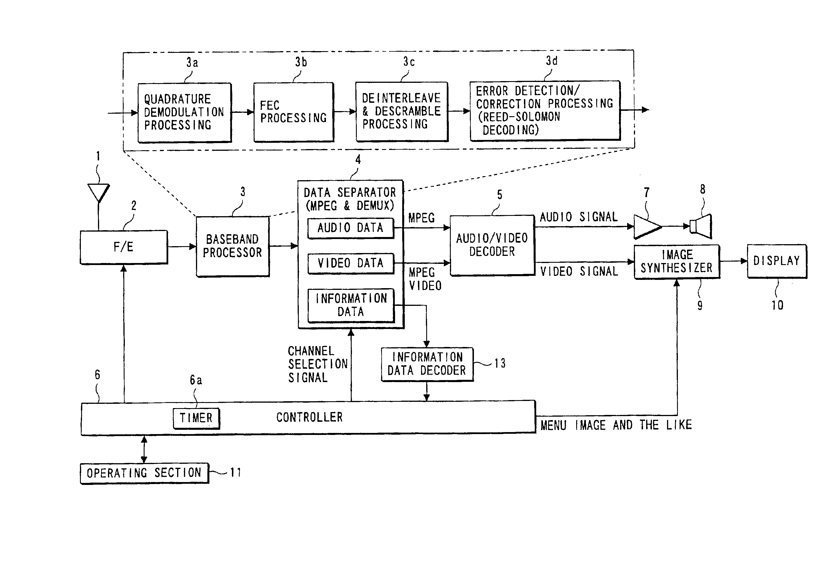
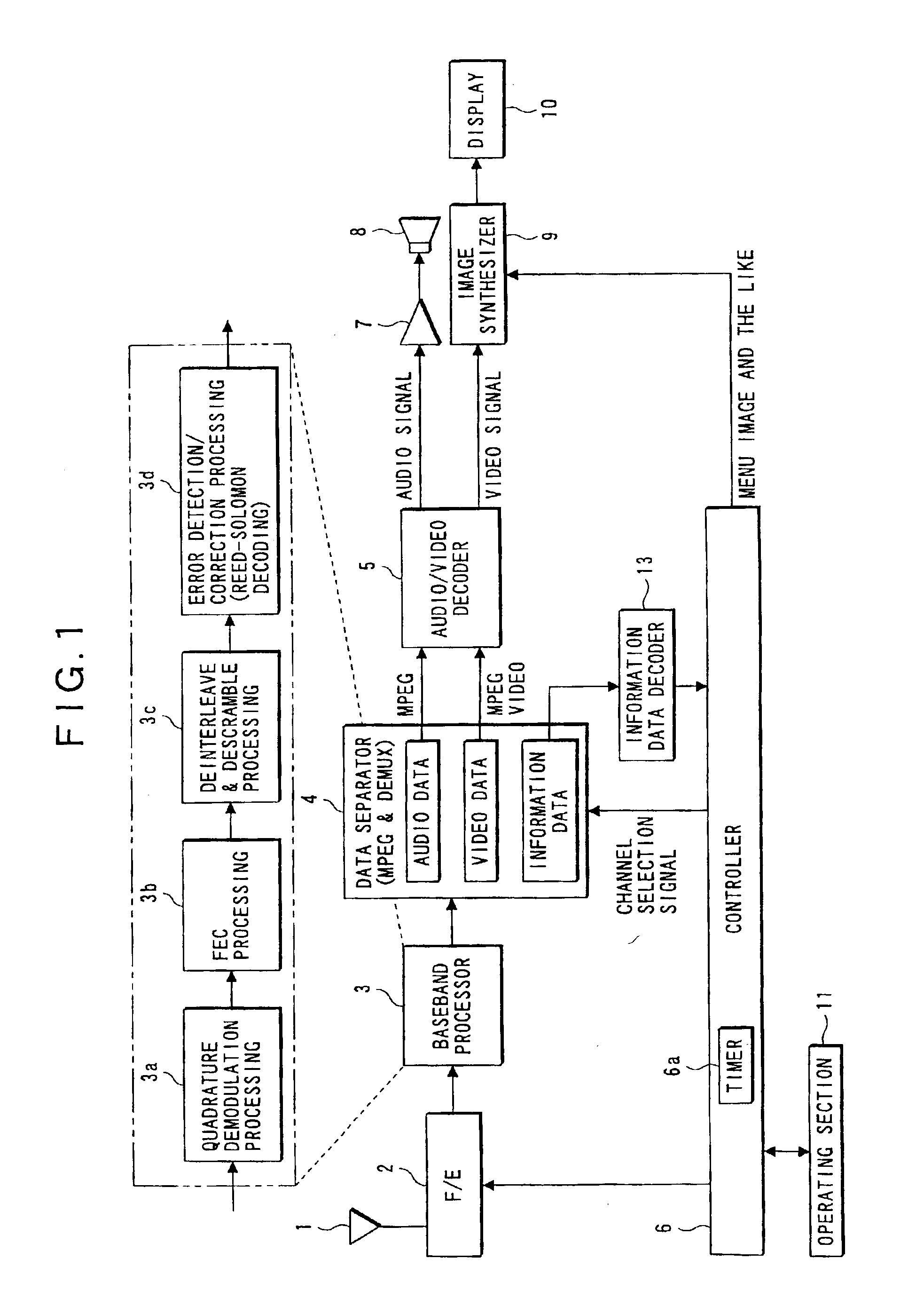
[0021]FIG. 1 is a diagram showing the construction of a digital broadcast receiver according to the present invention. An antenna 1 receives broadcast signal radio waves from a satellite. A front end (F / E) section 2 extracts a broadcast signal with a desired receive frequency component from the broadcast signals received via the antenna 1, and frequency-converts the extracted broadcast signal to provide an intermediate frequency signal. A baseband processor 3 comprises a quadrature demodulator 3a, a forward error correction (FEC) processor 3b, a de-interleave & descramble processor 3c, and an error detection / correction processor 3d. The baseband processor 3 subjects the intermediate frequency signal provided from the front end section 2 to the quadrature demodulation processing and the FEC (Forward...


PUM


Abstract

A channel scanning method in a multi-channel digital broadcast is provided for enabling a user to identify the broadcast contents of a channel being currently received with accuracy during the channel scan, even though the broadcast contents may change within a channel scanning time period. In one embodiment of the channel scanning method, a receive channel is switched at predetermined intervals (the scanning time period), it is checked whether the broadcast contents of the channel being received currently, after the channel switching, will change within the scanning time period, and a time period for receiving the channel is prolonged, if the broadcast contents will change.

Description

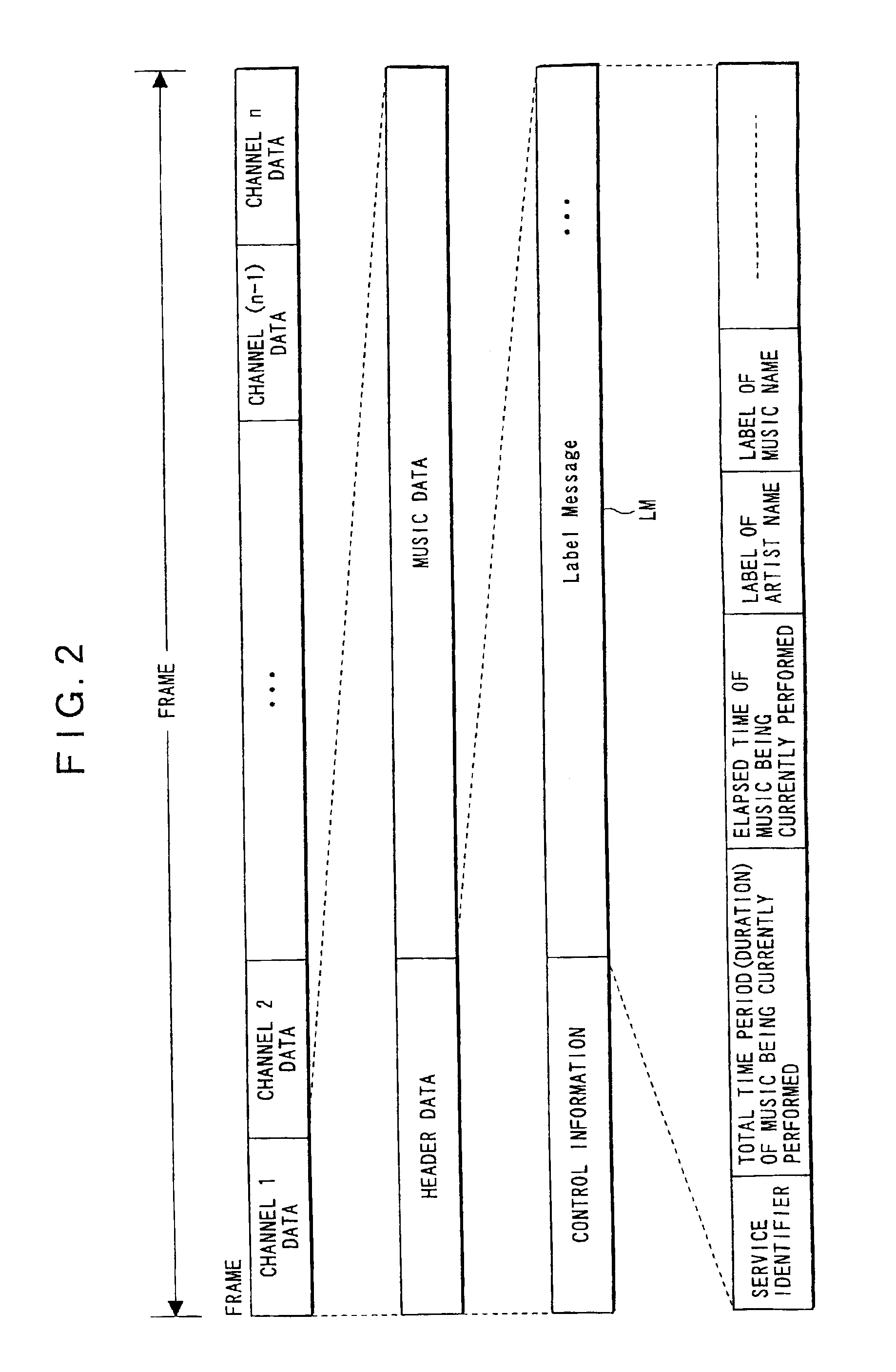
BACKGROUND OF THE INVENTION[0001]1. Field of the Invention[0002]The present invention relates to a broadcast receiver and a channel scanning method, and more particularly to a multi-channel broadcast receiver for switching a receive channel at predetermined intervals and a channel scanning method using same.[0003]2. Description of the Related Art[0004]In recent years, digital broadcasts have come into service that convert broadcast signals into digital signals and compress the digital signals to transmit them. Such digital broadcasts have less degradation in sound and image compared with conventional television and radio broadcasts. The compression of data as described also enables a digital broadcast to provide multi-channel broadcasts which handle more than one hundred channels. FIG. 7 is a diagram illustrating the construction of a frame in a digital broadcast. This figure shows that broadcast contents including “n” channels are subjected to mapping (in other words, time-division...

Claims


Application Information

Patent Timeline
IPC IPC(8): H03J1/00H04H1/00H04N5/44H04N5/50H03J7/18H04B1/16H04H20/26H04H20/33H04H60/39H04N21/434
CPCH03J1/0058H03J1/0091H04H60/39H04H60/43H04H60/74H04N5/4401H04N21/4345H04N21/4347H04N21/44016H04N21/8113H04H20/26H04H20/33H04N5/50H04N21/426
Inventor FUKUSHIMA, TAKAHIRO
Owner ALPINE ELECTRONICS INC
Learn More