
Floating virtualization layers

a virtualization layer and floating technology, applied in the field of data processing system, can solve the problems of a myriad of management problems, the administrator is faced with many unique storage problems, and the problem of providing subsets of large storage pools

Inactive Publication Date: 2005-08-02
ORACLE INT CORP
View PDF3 Cites 22 Cited by
  • Summary
  • Abstract
  • Description
  • Claims
  • Application Information

AI Technical Summary

Benefits of technology

"The present invention is a virtual system for managing stored data. It includes multiple hosts and data storage elements that are connected to the hosts. Each data storage element has its own unique management information that can be processed, used, changed, or modified at different locations within the system simultaneously. The system ensures consistent processing across multiple locations and can automatically discover and change the location of processing. This allows for more efficient and consistent data management across the system."

Problems solved by technology

Today's storage administrator is faced with many unique storage problems not prevalent a few years ago.
In addition to having to deal with multiple vendors with multiple products, the administrator is faced with a myriad of management issues.
Providing subsets of large storage pools becomes a problem.
In a site with multiple hosts and multiple storage devices, configuration software may also become an administrative issue.
In sites that have hosts and storage devices attached to a Fibre Channel loop, there is the problem of “How do I keep Host 1 from accessing and possibly restoring the data allocated to Host 2?” In this type of configuration, all of the hosts see all of the devices and believe they have access to them.
An additional challenge faced by administrators is the fact that there are often many unaligned sets of users and authorization for specific users to access or change data is a concern which is a challenge exasperated by the problems discussed above.

Method used


Image

  • Floating virtualization layers
  • Floating virtualization layers
  • Floating virtualization layers

Examples


Embodiment Construction

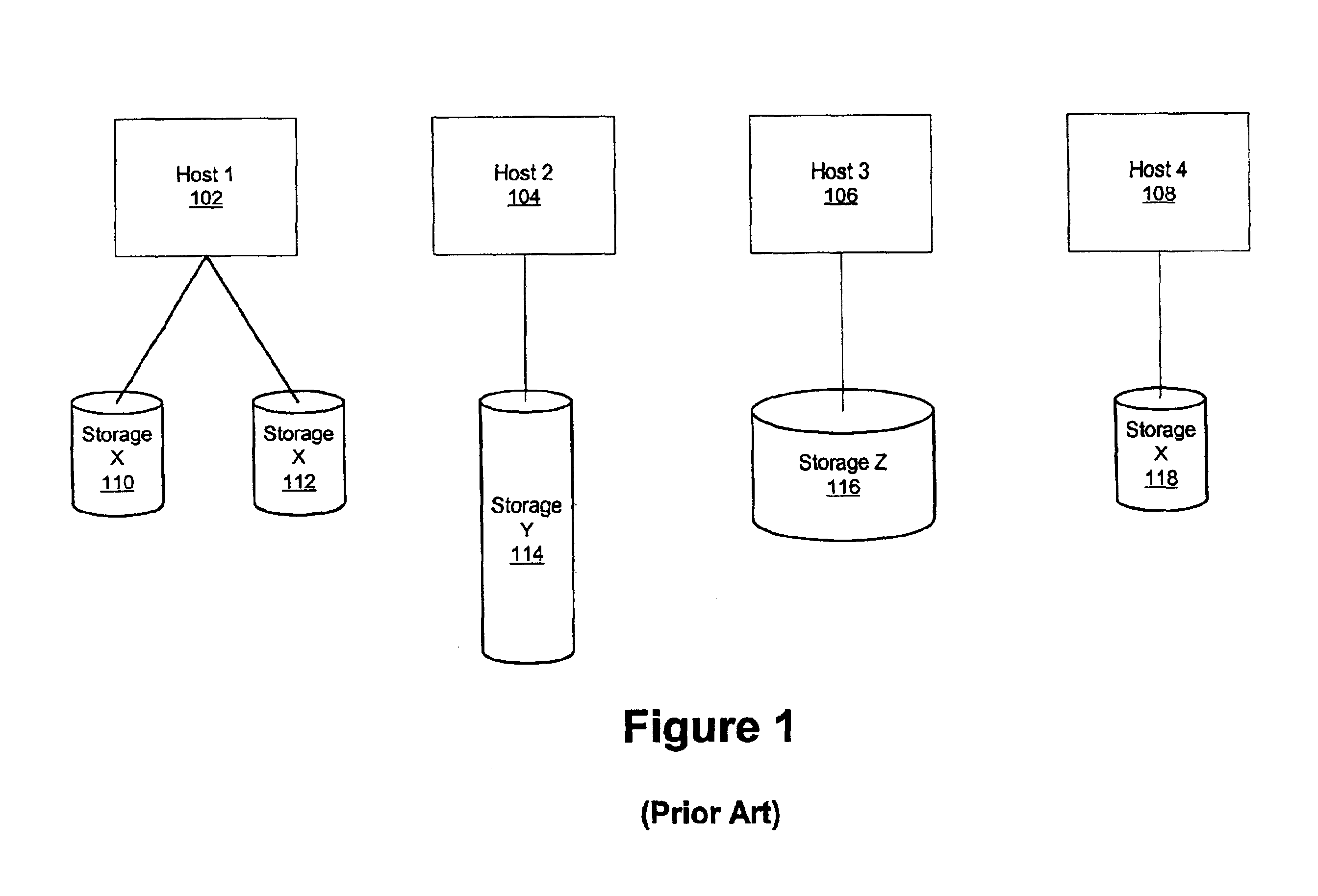
[0021]With reference now to the figures, FIG. 1 depicts a typical storage configuration according to the prior art. The site has several different hosts 102-108, each with dedicated storage 110-118 attached to it. The storage 110-118 has been purchased from different vendors at different times. Each of these hosts 102-108 has different management tools and cannot share storage 110-118 with the other hosts 102-108 as they need it.

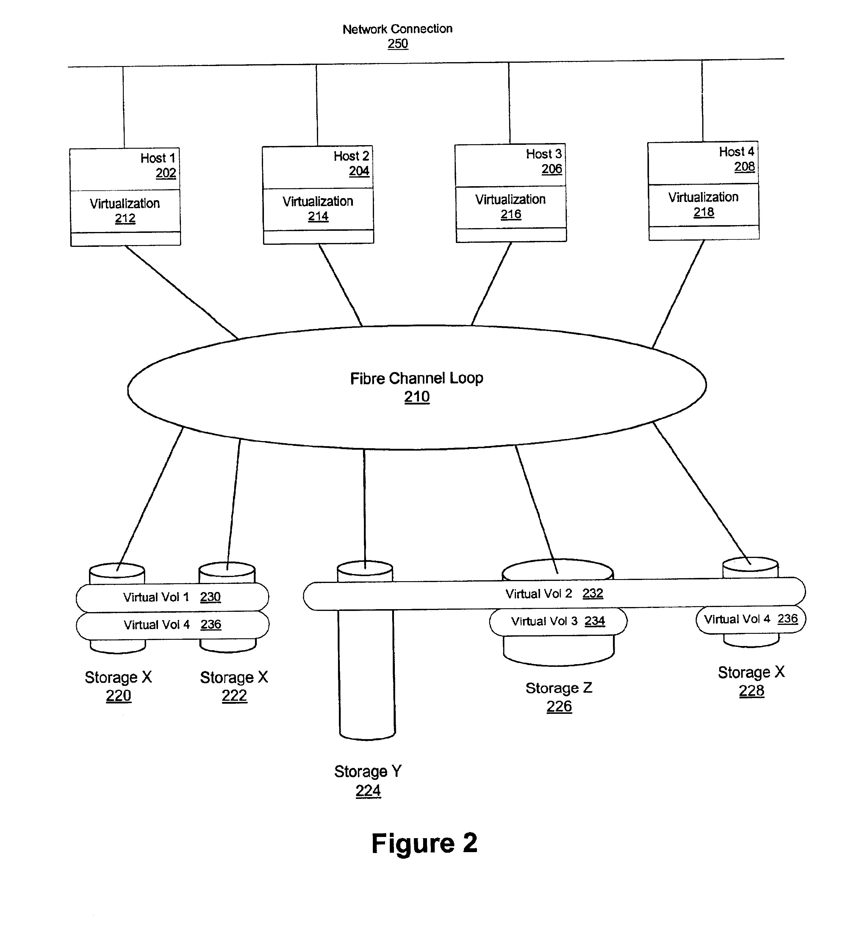
[0022]With reference now to FIG. 2, a block diagram illustrating an example of a virtualized storage environment that includes several hosts sharing storage across a number of storage devices is depicted in accordance with a preferred embodiment of the present invention. The physical devices 220-228 are treated as a pool of storage that may be carved up and assigned to individual hosts 202-208 as needed. Host-based virtualization (separating the user and physical views of the storage devices) provides this capability. In the depicted example, the virtual vol...


PUM


Abstract

A virtual stored data management system is provided. In one embodiment, the management system includes one or more hosts and a plurality of data storage elements functionally coupled to the hosts. Each data storage element includes a host network attachment, data transfer means, a storage controller, and permanent data storage media. The permanent data storage media is organized with management information uniquely associated with units of the data such that the management information may be manipulated in several different locations within the management system substantially simultaneously. Thus, the organization of the management processes allows for the management information to be processed, used, changed, or modified in several different locations within the management system at any particular instance. Provision is made for the internal processes to discover the current location of the processing, for the location to be changed as directed, and for the processing to be kept consistent when done in more than one place simultaneously.

Description

CROSS REFERENCE TO PROVISIONAL AND RELATED APPLICATIONS[0001]This application claims the benefit of the filing date of corresponding U.S. provisional Patent Application No. 60 / 212,772, entitled “System for providing a policy-based demand and use of functions like virtual volumes, instant copy, RAID, etc.”, filed Jun. 20, 2000. In addition, the present invention is related to applications entitled SYSTEM TO SUPPORT DYNAMICALLY FLEXIBLE DATA DEFINITIONS AND STORAGE REQUIREMENTS, Ser. No. 09 / 751,635; APPARATUS AND METHOD FOR DYNAMICALLY CHANGEABLE VIRTUAL MAPPING SCHEME, Ser. No. 09 / 884,294; USING CURRENT RECOVERY MECHANISMS TO IMPLEMENT DYNAMIC MAPPING OPERATIONS, Ser. No. 09 / 800,714 now U.S. Pat. No. 6,532,527; DYNAMICALLY CHANGEABLE VIRTUAL MAPPING SCHEME, Ser. No. 09 / 751,772; RECOVERY OF DYNAMIC MAPS AND DATA MANAGED THEREBY, Ser. No. 09 / 752,253; and SELF DEFINING DATA UNITS, Ser. No. 09 / 751,641, which are assigned to the same assignee, and incorporated herein by reference.BACKGROU...

Claims


Application Information

Patent Timeline
Patent Type & Authority Patents(United States)
IPC IPC(8): G06F12/10G06F12/08G06F3/06
CPCG06F3/0605G06F3/0622G06F3/0629G06F3/0665G06F3/067
Inventor SELKIRK, STEPHEN S.MILLIGAN, CHARLES A.MERRITT, PERRYGLADSTONE, EDWARD T.LENEHAN, JAMES B.
Owner ORACLE INT CORP
Learn More