Fuel injection valve spark plug combination

a fuel injection valve and spark plug technology, which is applied in the direction of electric ignition installation, mechanical equipment, machines/engines, etc., can solve the problems of inability to reliably ignite the so-called jet root of the fuel jet spray-discharged from the spray-discharge orifice, and the discharge orifice of the fuel jet may be subject to steadily worsening carbon fouling

Inactive Publication Date: 2005-08-09
ROBERT BOSCH GMBH
View PDF16 Cites 48 Cited by
  • Summary
  • Abstract
  • Description
  • Claims
  • Application Information

AI Technical Summary

Benefits of technology

[0004]In contrast, the fuel injector-spark plug combination of the present invention, having the characterizing features of the main claim, has the advantage over the related art that by a biaxial arrangement of the fuel injector and the spark-plug insulator of the spark plug in a shared connecting member, which is insertable in the cylinder head of the internal combustion engine, the components are optimally arranged with respect to each other, resulting in a system which is easy to install and requires little space.
[0007]Particularly advantageous is the tilting of the longitudinal axis of the spark-plug insulator relative to the longitudinal axis of the fuel injector, since it avoids that the spark plug is directly exposed to the fuel jet of the fuel injector.
[0008]Furthermore, it is advantageous that, by a suitable form of the connecting member, the fuel injector is able to be held in place inside it, for instance by means of a mounting clamp, which rests on a shoulder of the fuel injector.
[0010]It is also advantageous that both the fuel injector and the individual parts of the spark plug, i.e., the spark-plug insulator and the ground electrode, are able to be exchanged independently of one another, without having to remove the connecting member from the cylinder head or having to remove one of the other components.

Problems solved by technology

However, a disadvantage of the known fuel injector with integrated spark plug is that the position of the spark arc-over is not defined with respect to the fuel jet spray-discharged from the discharge orifice, since the spark arc-over may occur just about anywhere in the lateral region of a projection of the valve body.
A reliable ignition of the so-called jet root of the fuel jet spray-discharged from the spray-discharge orifice is not possible with the required reliability in this known design.
Furthermore, the discharge orifice of the fuel jet may be subject to steadily worsening carbon fouling or coking, which influences the form of the spray-discharged jet.

Method used


Image

  • Fuel injection valve spark plug combination
  • Fuel injection valve spark plug combination
  • Fuel injection valve spark plug combination

Examples


Embodiment Construction

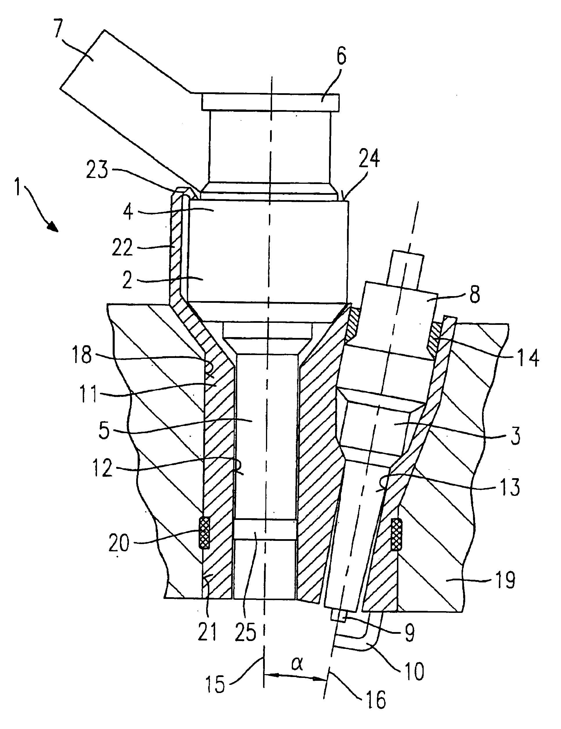
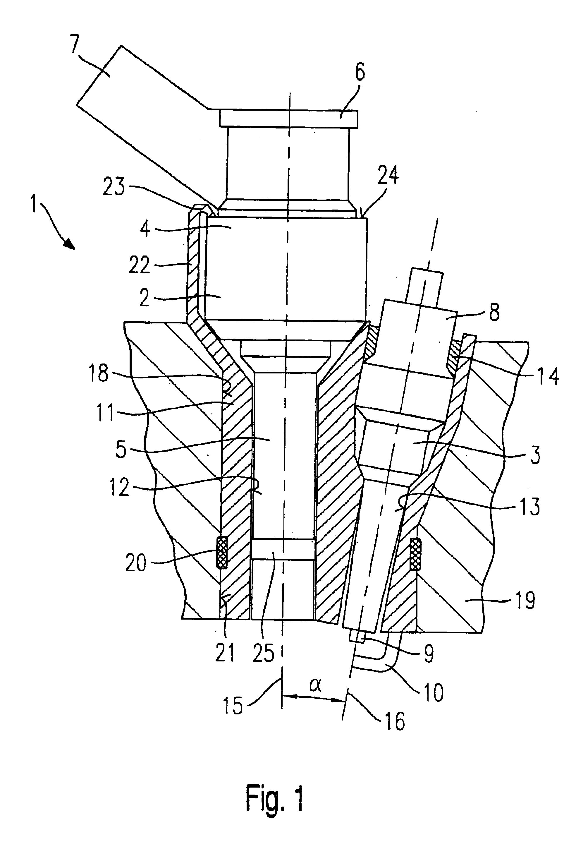
[0015]FIG. 1 shows a fuel injector-spark plug combination 1 having a fuel injector 2 for the direct injection of fuel into a combustion chamber of a mixture-compressing internal combustion engine having external ignition and a spark plug 3 for igniting the fuel spray-discharged into the combustion chamber according to a first exemplary embodiment of the present invention.

[0016]Fuel injector 2 has a housing body 4 and a nozzle body 5. Fuel is conveyed to fuel injector 2 via an inflow nipple 6, which is connected to a fuel-distributor line (not shown further in FIG. 1). Fuel injector 2 has an electric plug-in contact 7 which allows the contacting of the actuation device of fuel injector 2 which is not shown in FIG. 1.

[0017]Spark plug 3 has a conventional design and is made up of a spark-plug insulator 8, which is preferably made of a ceramic material, and a first electrode 9 positioned therein. First electrode 9 is electrically contactable by an ignition device (not shown further). At...


PUM


Abstract

A fuel injector-spark plug combination includes a fuel injector for the direct injection of fuel into a combustion chamber of an internal combustion engine and a spark plug with a spark-plug insulator, the spark plug having a first electrode, and a second electrode for igniting the fuel injected into the combustion chamber. The fuel injector and the spark-plug insulator of the spark plug are arranged at a biaxial offset in a respective receiving bore of a shared connecting member inserted in a recess of a cylinder head.

Description

FIELD OF THE INVENTION[0001]The present invention is based on a fuel injector-spark plug combination.BACKGROUND INFORMATION[0002]From the European Published Patent Application No. 0 661 446, a fuel injector having an integrated spark plug is known. The fuel injector with integrated spark plug is used for the direct injection of fuel into the combustion chamber of an internal combustion engine and for igniting the fuel injected into the combustion chamber. Due to the compact integration of a fuel injector with a spark plug it is possible to save installation space at the cylinder head of the internal combustion engine. The known fuel injector with integrated spark plug has a valve body which, together with a valve-closure member actuable by means of a valve needle, forms a sealing seat, adjacent to which is a spray-discharge orifice, which discharges at an end face of the valve member facing the combustion chamber. A ceramic insulation element insulates the valve body from a housing ...

Claims


Application Information

Patent Timeline
Patent Type & Authority Patents(United States)
IPC IPC(8): F02M61/00F02M57/06F02M57/00F02M61/14F02B23/10F02F1/24F02B75/12F02B75/00F02P13/00F02B23/02
CPCF02B23/101F02F1/242F02M57/06F02M61/14F02B2075/125F02M2200/858Y02T10/125Y02T10/123Y02T10/12
Inventor HERDEN, WERNERVOLZ, DIETERWUERFEL, GERNOTMELSHEIMER, ANJASCHMITTINGER, SIMONNORGAUER, RAINERDEPONTE, RENE
Owner ROBERT BOSCH GMBH
Why Eureka
Try Eureka