Downhole actuation system utilizing electroactive fluids

a technology of electroactive fluids and actuators, applied in the direction of valve operating means/release devices, borehole/well accessories, sealing/packing, etc., can solve the problems of many and diverse challenges of deepwell drilling, and controllable fluids have the potential to radically change the way electromechanical devices are designed and operated, and achieve the effect of less viscosity

Inactive Publication Date: 2005-08-09
BAKER HUGHES INC
View PDF34 Cites 52 Cited by
  • Summary
  • Abstract
  • Description
  • Claims
  • Application Information

AI Technical Summary

Benefits of technology

[0015]The present invention provides a method and apparatus for actuation of a downhole tool by placing an electroactive fluid in a container within the tool where the fluid becomes either highly viscous or a solid when a small magnetic field is applied. After deactivation or removal of an electromagnetic field current, the fluid becomes much less viscous. At the lower viscosity value, the fluid may be induced to flow from a mechanical restraint chamber thereby permitting the movement of a slip setting piston. Such movement of a setting piston may be biased by a mechanical spring, by in situ wellbore pressure or by pump generated hydraulic pressure, for example.

Problems solved by technology

Transmitting power and control signals to dynamic tools working near the wellbore bottom is an engineering challenge.
However, the challenges of deepwell drilling are many and diverse.
Controllable fluids have the potential to radically change the way electromechanical devices are designed and operated.

Method used


Image

  • Downhole actuation system utilizing electroactive fluids
  • Downhole actuation system utilizing electroactive fluids
  • Downhole actuation system utilizing electroactive fluids

Examples


Embodiment Construction

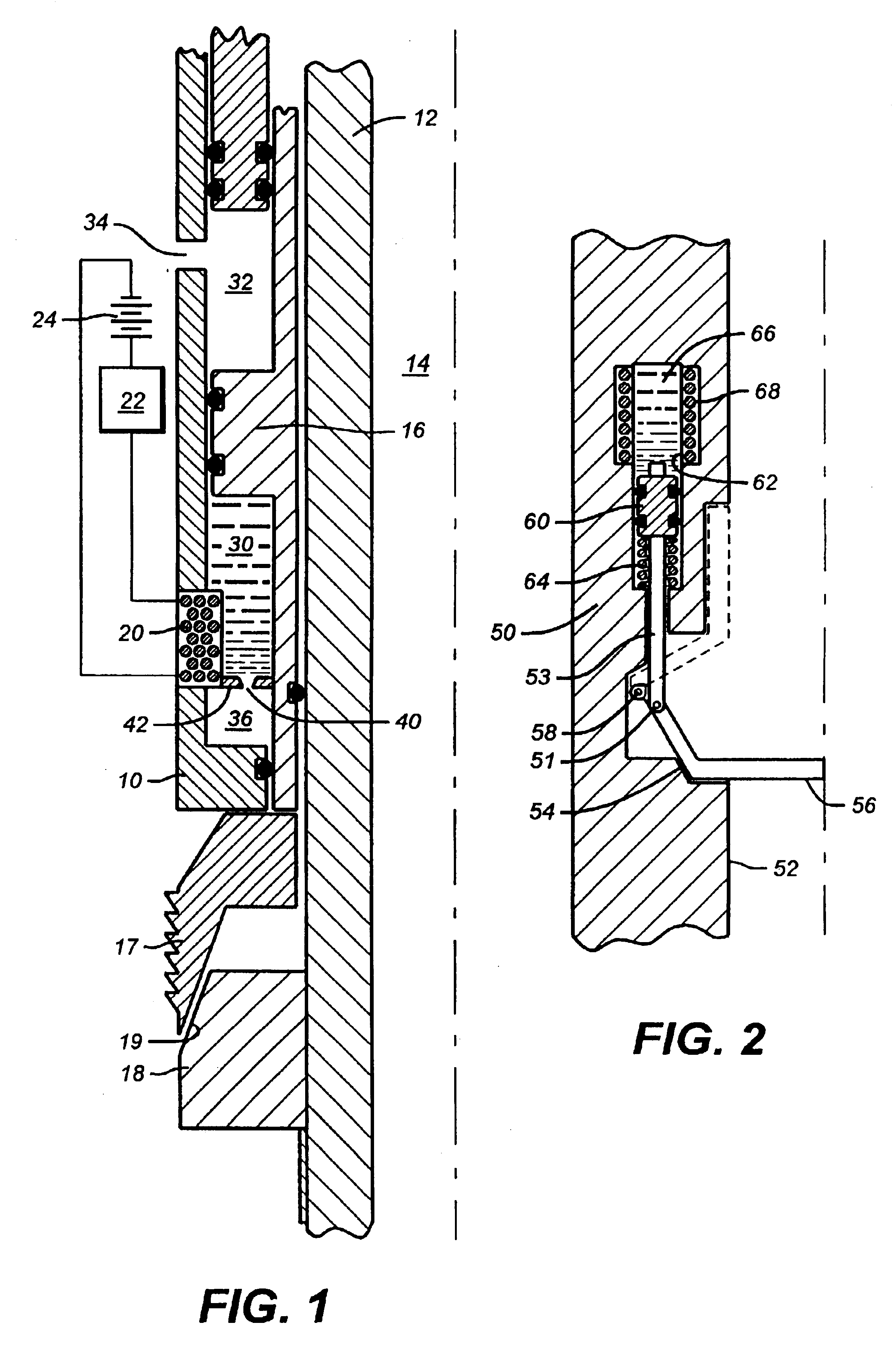
[0027]Referring to FIG. 1, the slip actuating section of a downhole tool is illustrated in schematic quarter section. Typically, the tool is assembled within a casement or housing pipe 10. Concentrically within the casement is an internal mandrel 12 around a central fluid flow bore 14. Slip wickers 17 are distributed around the mandrel circumference to overlie the ramped face 19 of an actuating cone 18. The cone 18 is secured to the mandrel 12. The slip wickers 17 are translated axially along the mandrel by the ram edge of a piston 16. As the piston 16 advances axially along the mandrel surface against the wickers 17, the wickers slide along the face of ramp 19 for a radially outward advancement against a well bore wall or casing.

[0028]One face of the piston 16 is a load bearing wall of a wellbore pressure chamber 32. One or more flow ports 34 through the casement wall 10 keep the chamber 32 in approximate pressure equilibrium with the wellbore fluid pressure. The opposing face of p...


PUM


Abstract

Downhole wellbore tools are actuated by electrically controllable fluids energized by a magnetic field, for example. When energized, the viscosity state of the fluid may be increased by a degree depending on the fluid formulation. Reduction of the controllable fluid viscosity by terminating a magnetic field acting upon the fluid may permit in situ wellbore pressure to actuate a downhole device, such as a wellbore packer.

Description

[0001]The present application is a continuation of U.S. patent application Ser. No. 09 / 916,617 filed Jul. 27, 2001, which issued as U.S. Pat. No. 6,568,470 on May 27, 2003.BACKGROUND OF THE INVENTION[0002]1. Field of the Invention[0003]The present invention relates to the art of earth boring. In particular, the invention relates to methods and apparatus for remotely controlling the operation of downhole tools.[0004]2. Description of Related Art[0005]In pursuit of deeply deposited economic minerals and fluids such as hydrocarbons, the art of earthboring involves many physical operations that are carried out remotely under hazardous and sometimes hostile conditions. For example, hydrocarbon producing boreholes may be more than. 25,000 ft. deep and have a bottom-hole pressure more than 10,000 psi and a bottom-hole temperature in excess of 300 F.[0006]Transmitting power and control signals to dynamic tools working near the wellbore bottom is an engineering challenge. Some tools and circ...

Claims


Application Information

Patent Timeline
Patent Type & Authority Patents(United States)
IPC IPC(8): E21B33/1295E21B23/04E21B23/00E21B33/12F15B21/00F15B21/06E21B34/00
CPCE21B23/04E21B33/1295F15B21/065E21B2034/005Y10S137/909E21B2200/05E21B34/066E21B23/042
Inventor GOODSON, JR., JAMES EDWARDCARMODY, MICHAEL
Owner BAKER HUGHES INC
Why Eureka
Try Eureka