Center sill car jack utilizing air bellows

a technology of air bellows and car jacks, which is applied in the direction of lifting devices, devices secured to tracks, lifting frames, etc., can solve the problems of not being able to move easily from one site to another, requiring several people to operate the jacks, and certain inherent risks of the use of either the crane or the paired lift jacks, etc., to achieve the effect of being portable to different use sites

Inactive Publication Date: 2005-08-09
TTX CO
View PDF16 Cites 3 Cited by
  • Summary
  • Abstract
  • Description
  • Claims
  • Application Information

AI Technical Summary

Benefits of technology

[0011]One aspect of the present invention provides a jack assembly that is self contained and relatively lightweight, to be quite portable to different use sites. The disclosed jack assembly may also be operated by one person at almost any rail site.
[0012]Another aspect of the present invention provides that the disclosed jack assembly cooperates directly between the track rails and the car frame, providing safe non-yielding, solid metal-to-metal, triangulated support of the railroad car above the track rails, and without the need of braces or supports to be placed on the rail bed surface.
[0015]Another embodiment may include rotating support members that provide additional support to the power lift means. The support members have an abutting relationship with the car engaging means when the power lift means is fully extended to help distribute the load of the railroad car and provide lateral and rotational stability. Air cylinders can be used to actuate the support members between a lowered position and a raised position.
[0017]In another embodiment, a method of raising a railroad car is provided. The method comprising the steps of providing a pair of frame members, a power lift means attached to the frame members, a railroad car engaging means and an air source to activate the power lift means. Air pressure from the air source is introduced to the power lift means to extend the power lift means, thereby raising the car engaging means in a vertical direction. Posts are placed around the power lift means and attached to the car engaging means so as to provide lateral and rotational support while raising and lowering the railroad car.

Problems solved by technology

This requires the presence of a high capacity crane that can carry the load of the car, and such a crane will typically be quite large and represent a significant capital investment.
If the crane limited to rolling along on track rails, it may not be conveniently moved from one site to another.
Moreover, with the jacks on opposite sides of the car, several people may be needed to operate the jacks.
Moreover, there are certain inherent risks with the use of either the crane or paired lift jacks because they bear the entire load of the railroad car during the time the wheeled truck is removed from the car or while someone is under the car for servicing.
A crosswind may cause the crane-suspended car to sway, or the paired jack-supported car may topple sideways off of the jacks.
This can be both dangerous to personnel and destructive to property.
Dangerously, any failure of the crane lift line or of either jack can allow the raised car to fall.
For example, the hydraulic pump system used is expensive, heavy and often requires significant maintenance.
Also, the hydraulic lift system is raised and lowered in a somewhat long period of time.

Method used


Image

  • Center sill car jack utilizing air bellows
  • Center sill car jack utilizing air bellows
  • Center sill car jack utilizing air bellows

Examples


Embodiment Construction

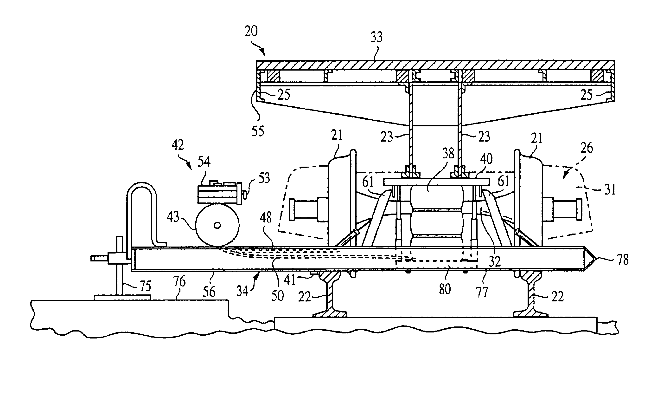
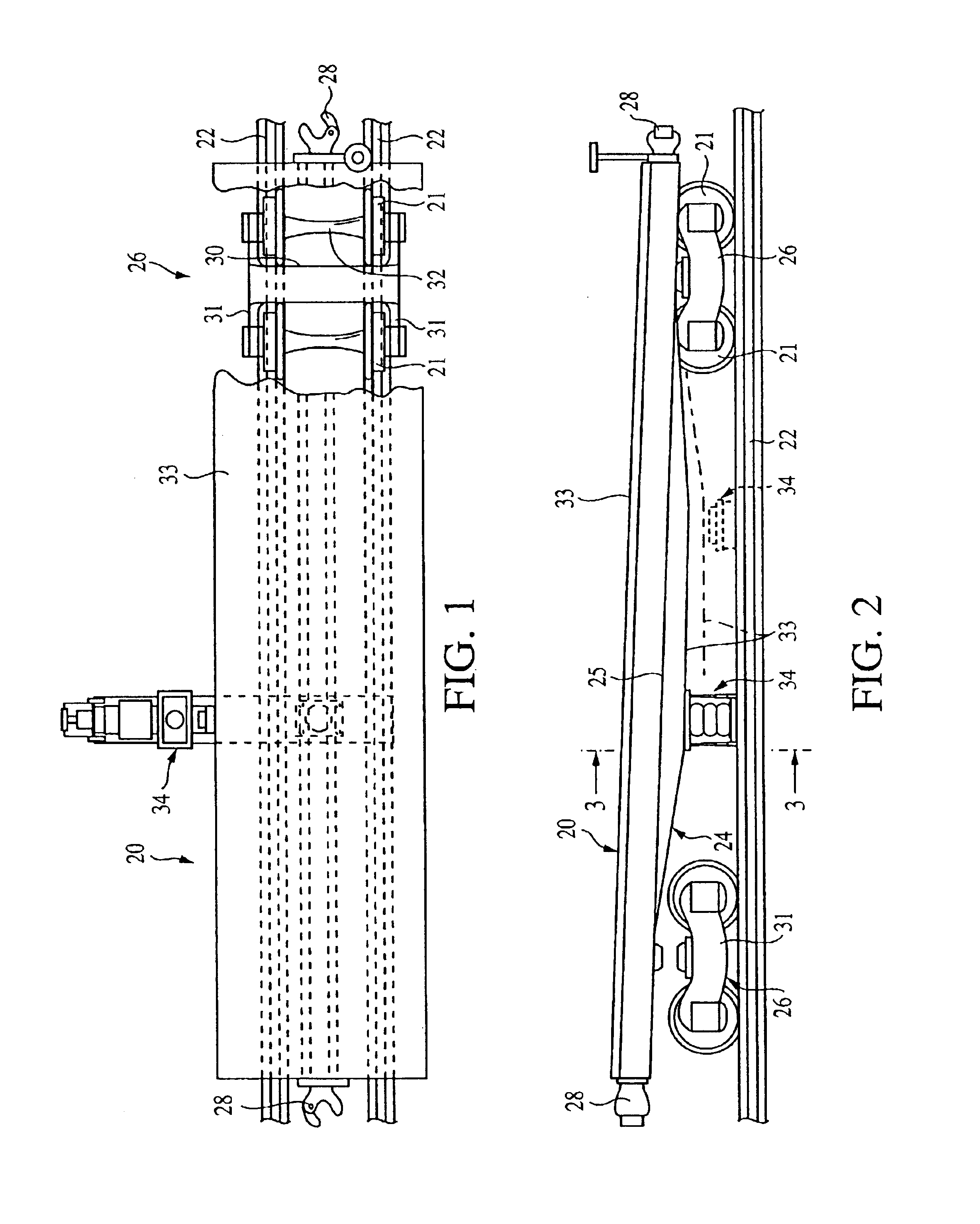
[0026]FIG. 1 is a top view of the railroad car jack 34 in a preferred operative position beneath a railroad car 20. A section of railroad car flooring 33 has been cut away to show the location of a wheeled truck assembly 26 with respect to the railroad car frame 24 and the railroad track rails 22.

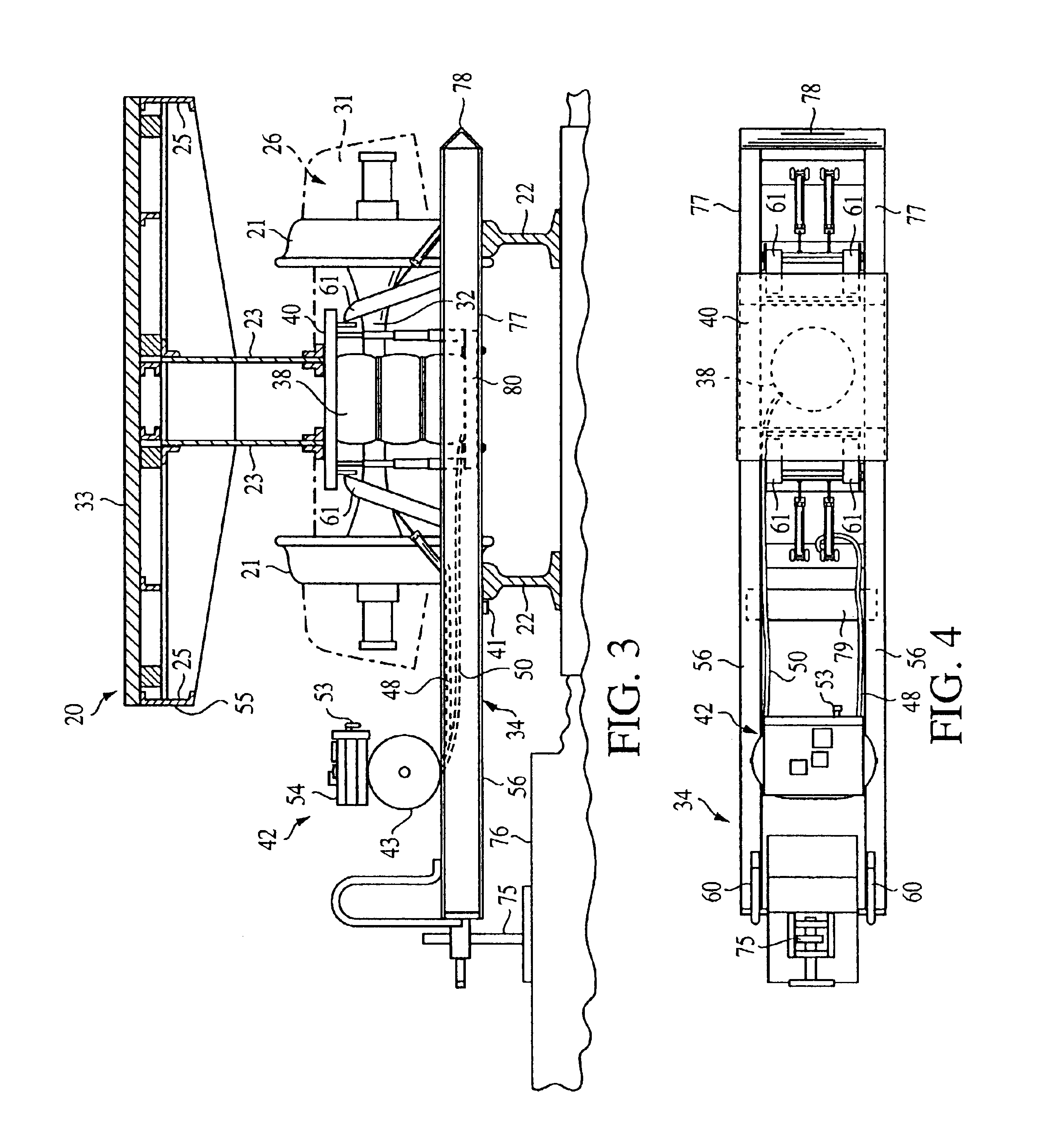
[0027]In a first embodiment, a flat-bed railroad car 20, as illustrated in FIGS. 1, 2 and 3, has flanged wheels 21 adapted to roll on two laterally spaced track rails 22. The railroad car 20 has a frame 24 including a central sill 23 and side channels 25, each elongated in the direction of the track rails 22. A wheeled truck assembly 26 is connected to the central sill 23 of the frame 24 at each end of the railroad car 20. Couplings 28 are connected to the frame 24 at the opposite ends of the car 20.

[0028]Each wheeled truck assembly 26 includes a cross member 30 and a pair of side frame members 31. The cross member 30 is coupled at its ends through spring and snubbing means (not shown) to t...


PUM


Abstract

The disclosed jack assembly is used to raise the frame of a railroad car to a sufficient height above a wheeled truck assembly coupled to the railroad car in order to perform maintenance or remove the truck assembly. The jack assembly comprises an air-operated bellows which raises and lowers a plate that engages the railroad car for the raising and lowering action. Telescoping posts and other support members aid in stabilizing the jack assembly during use in order to prevent failure of the bellows due to buckling under the weight of the railroad car. The jack assembly is readily mobile between locations, and can be operated by a single user.

Description

FIELD OF THE INVENTION[0001]The present invention relates to the field of lifting devices, and more particularly to a railroad car jack assembly.BACKGROUND OF THE INVENTION[0002]A typical railroad car has an elongated frame and a pair of wheeled truck assemblies attached to the frame. Each truck assembly is attached to the frame at each end of the car. Each wheeled truck assembly in turn includes flanged wheels that are adapted to roll on a pair of railroad track rails.[0003]With the wheels on the track rails, there may be clearance of only a few inches between the top of the railroad track rails and the underside of the railroad car frame. Routine maintenance may require that the car frame be elevated somewhat in order to increase this clearance. One form of maintenance may require that the railroad car be completely removed from one of the truck assemblies, to allow such truck assembly to be replaced with another. For example, to remove the assembly, the one end of the car may be ...

Claims


Application Information

Patent Timeline
Patent Type & Authority Patents(United States)
IPC IPC(8): B61K5/04B61K5/00B66F3/35B66F3/24
CPCB61K5/04B66F3/35
Inventor SHAH, JACK K.BENSON, T. MICHAEL
Owner TTX CO
Why Eureka
Try Eureka