Ink cartridge and method of ink injection thereinto

Inactive Publication Date: 2005-08-09
SEIKO EPSON CORP
View PDF17 Cites 29 Cited by
  • Summary
  • Abstract
  • Description
  • Claims
  • Application Information

AI Technical Summary

Benefits of technology

[0026]According to such a method, there can be provided an ink cartridge wherein bubbles can be prevented

Problems solved by technology

In such a record apparatus, pressure fluctuation occurs in internal ink as an ink supply tube is extended and bent with acceleration and deceleration of the carriage, making unstable eje

Method used


Image

  • Ink cartridge and method of ink injection thereinto
  • Ink cartridge and method of ink injection thereinto
  • Ink cartridge and method of ink injection thereinto

Examples


Embodiment Construction

[0045]Referring now to the accompanying drawings, there are shown preferred embodiments of an ink cartridge and an ink injection method thereinto incorporating the invention.

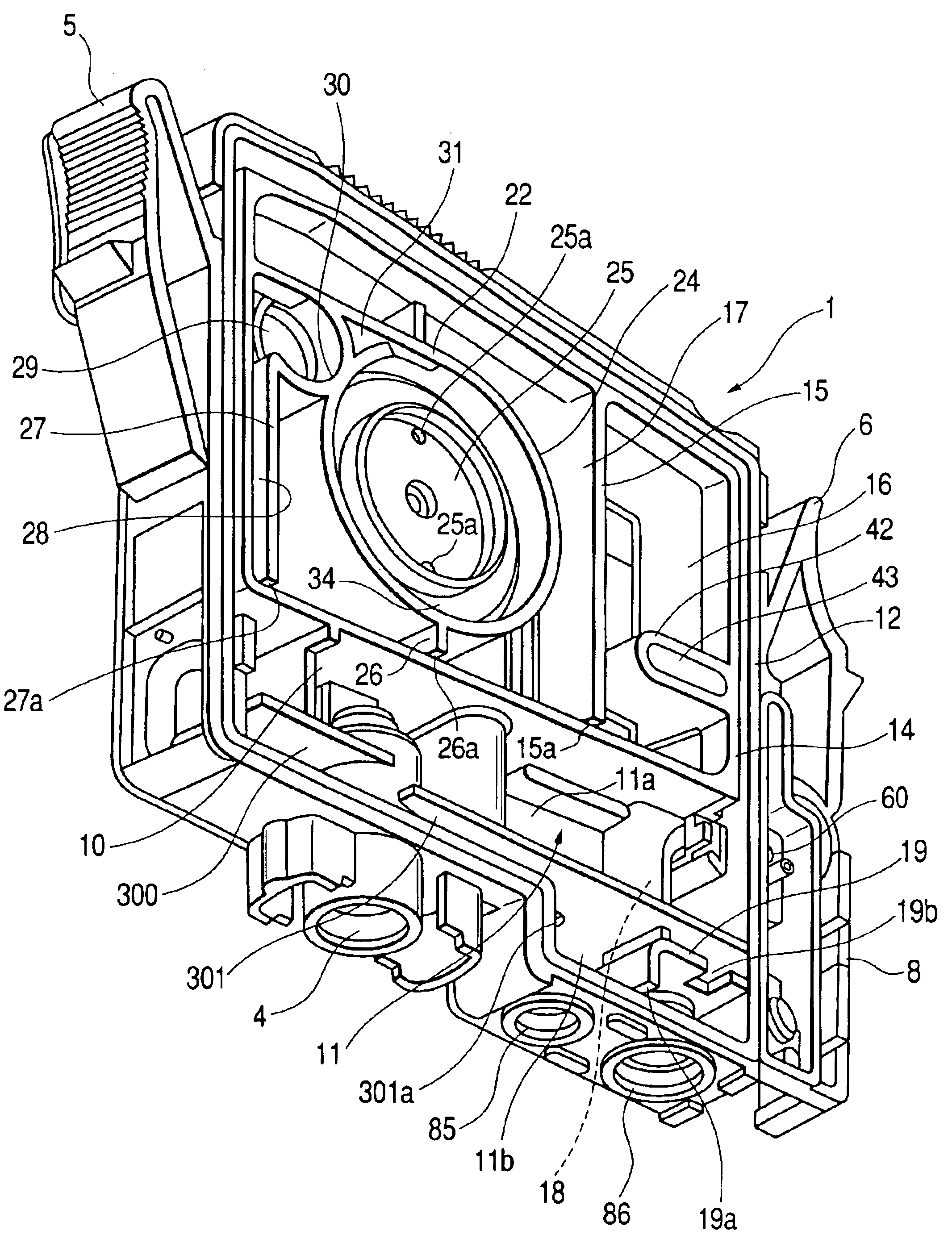
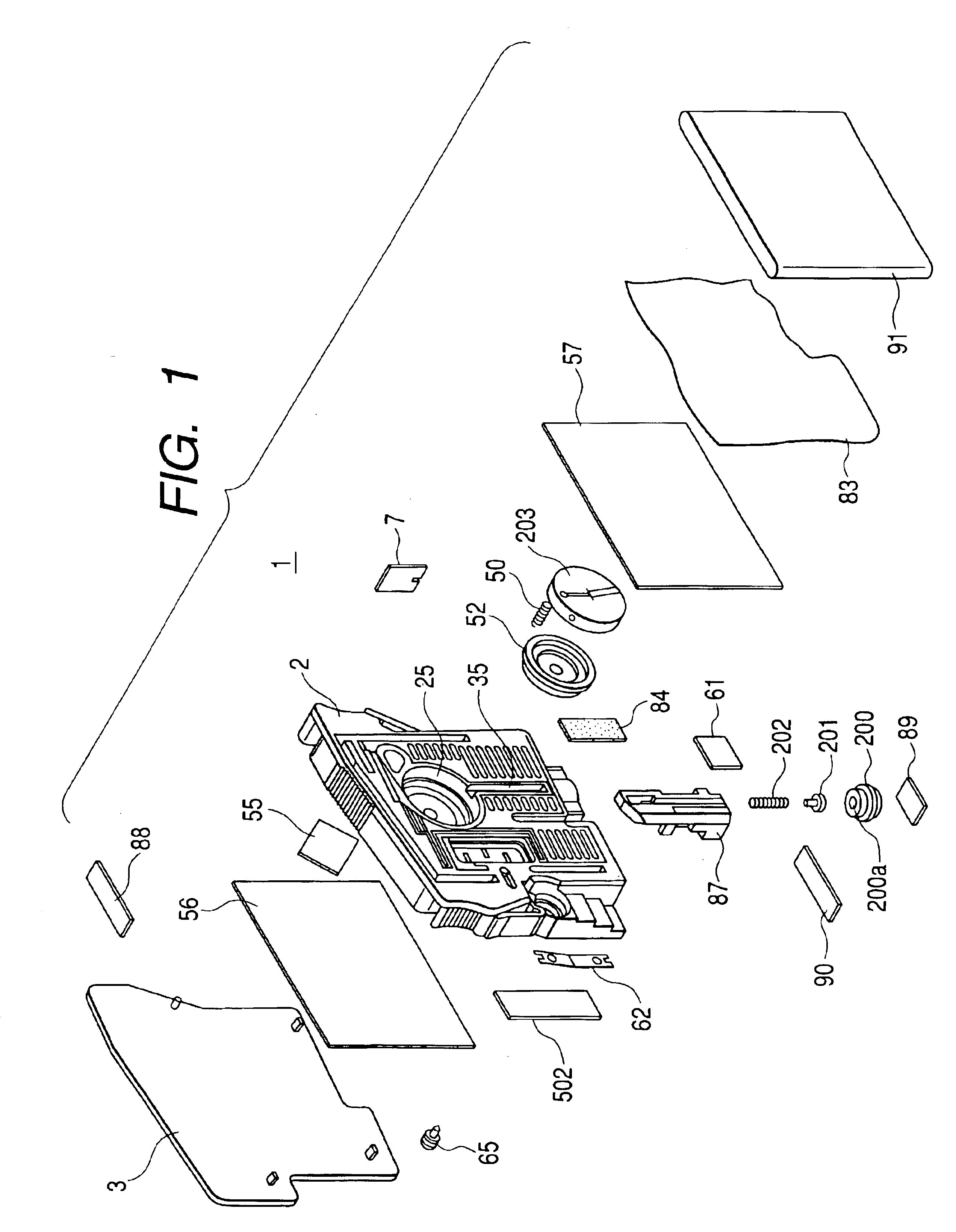
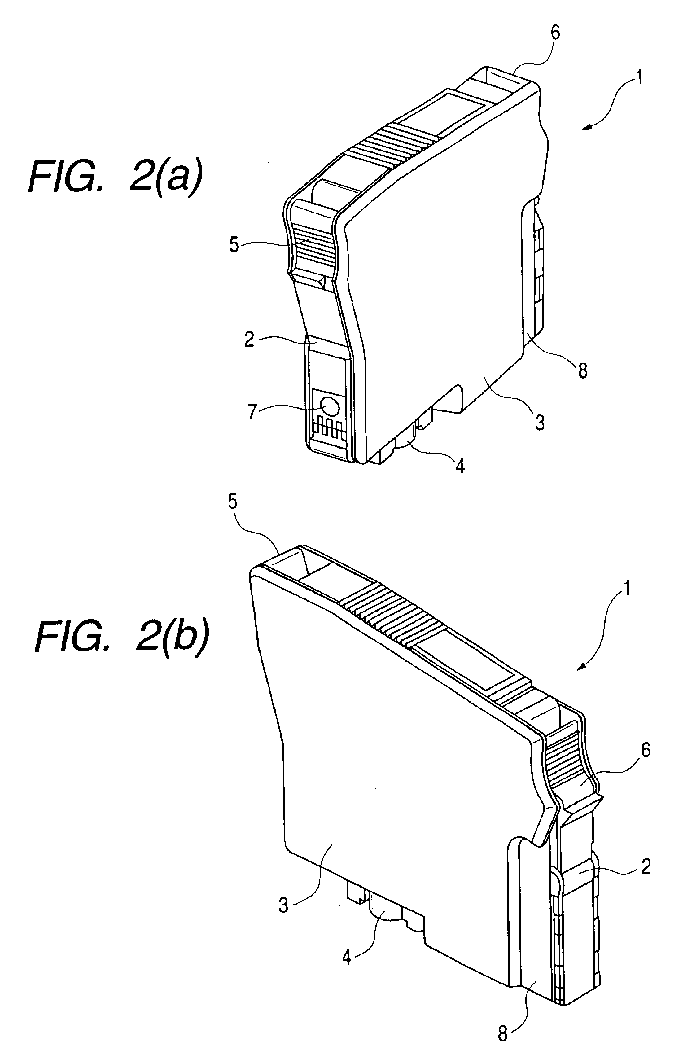
[0046]To begin with, the ink cartridge will be discussed with reference to FIGS. 1 to 11. FIG. 1 is an exploded perspective view to show the whole of the ink cartridge according to the embodiment of the invention. FIGS. 2(a) and 2(b) are perspective views to show the appearance of the ink cartridge according to the embodiment of the invention. FIGS. 3 and 4 are perspective views showing the internal structure of the ink cartridge according to the embodiment of the invention as viewed from upward and downward in a slanting direction. FIGS. 5 and 6 are a front view and a rear view to show the internal structure of the ink cartridge according to the embodiment of the invention. FIGS. 7 and 8 are enlarged sectional views to show a negative pressure generation system storage chamber and a valve storage chamber of the...


PUM


Abstract

An ink cartridge 1 is detachably connected to a head of a record apparatus and has a vessel main body 2 having an ink tank chamber 11 opened to the atmosphere in a state in which the head and the cartridge are connected and an ink end chamber (second ink storage chamber 16, etc.,) communicating with the ink tank chamber 11 and leading to the head. The vessel main body 2 is formed with a first opening 85 communicating with the ink tank chamber 11 and a second opening 86 communicating with the ink end chamber.

Description

BACKGROUND OF THE INVENTION[0001]This invention relates to an ink cartridge for supplying ink to a head of a record apparatus and a method of ink injection thereinto.[0002]An ink jet record apparatus generally comprises a record head mounted on a carriage and moving in the width direction of record paper, and paper feed means for moving the record paper relatively in a direction orthogonal to the move direction of the record head.[0003]Such an ink jet record apparatus prints on record paper by ejecting ink droplets from a record head based on print data.[0004]A record head capable of ejecting black ink, yellow ink, cyan ink, and magenta ink, for example, is mounted on a carriage and in addition to text print in black ink, full-color print is made possible by changing the ink ejection percentage.[0005]Thus, ink cartridges for supplying black ink, yellow ink, cyan ink, and magenta ink to the record head are placed in the main unit of the apparatus.[0006]In the ordinary ink jet record ...

Claims


Application Information

Patent Timeline
IPC IPC(8): B41J2/175
CPCB41J2/17509B41J2/17513B41J2/1752B41J2/17526B41J2/1755B41J2/17553B41J2/17556B41J2/17596B41J2/17563B41J2/175
Inventor OTA, MUTSUHIKOSUDA, YUKIHARUKOIKE, HISASHISHINADA, SATOSHITSUKAHARA, MICHINARIMIYAZAWA, HISASHI
Owner SEIKO EPSON CORP
Why Eureka
Try Eureka