Retractable road barrier

a road barrier and retractable technology, applied in roadway safety arrangements, roads, construction, etc., can solve the problems of forming interruptions, affecting the safety of vehicles, etc., to achieve convenient removal and replacement, and efficient solving the effect of solving problems, and ensuring safety

Inactive Publication Date: 2005-08-09
CENT RICERCHE FIAT SCPA
View PDF13 Cites 30 Cited by
  • Summary
  • Abstract
  • Description
  • Claims
  • Application Information

AI Technical Summary

Benefits of technology

[0007]Due to the above indicated features, there exists an ample flexibility in the configurations which can be selected for the barrier, since any one of the sets of barrier elements can be displaced from the operative raised position to the lowered inoperative position, while the sets adjacent to the ends of the lowered set can be either kept raised or lowered, at will, the connecting elements between adjacent sets ensuring the continuity of the upper surface and the two side surfaces of the barrier in any case. Furthermore, since each set of barrier elements is constituted by barrier elements whose supporting columns are articulated to a bracket which is anchored to the ground, each of these sets forms a unit which can be easily removed and replaced.
[0008]A further object of the present invention is that of ensuring that the barrier elements can be a

Problems solved by technology

Moreover, in this known solution, in case only some of the barrier elements are lowered into the inoperative position, interruptions are formed at the areas interposed between each lowered element and an adjacent raised element.
Finally, the solution shown in the above indicated document has a structure such that any operations for replacing a damaged barrier portion, for example due to a road accident, become lengthy and troublesome.
In particular, although this solution shows a barrier with a connecting element which connects a retractable barrier element to a non-retractable barrier element

Method used


Image

  • Retractable road barrier
  • Retractable road barrier
  • Retractable road barrier

Examples


Embodiment Construction

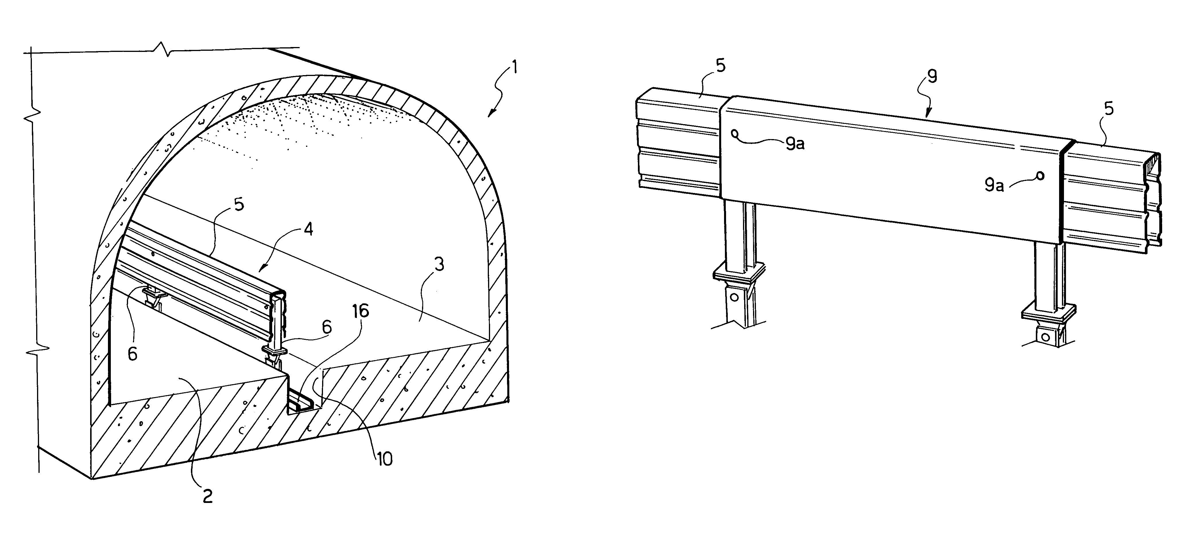
[0018]In FIG. 1, the reference number 1 designates as a whole a road tunnel having two lanes 2, 3 for passage of traffic in two opposite directions, which are separated by a safety barrier 4 built according to the invention.

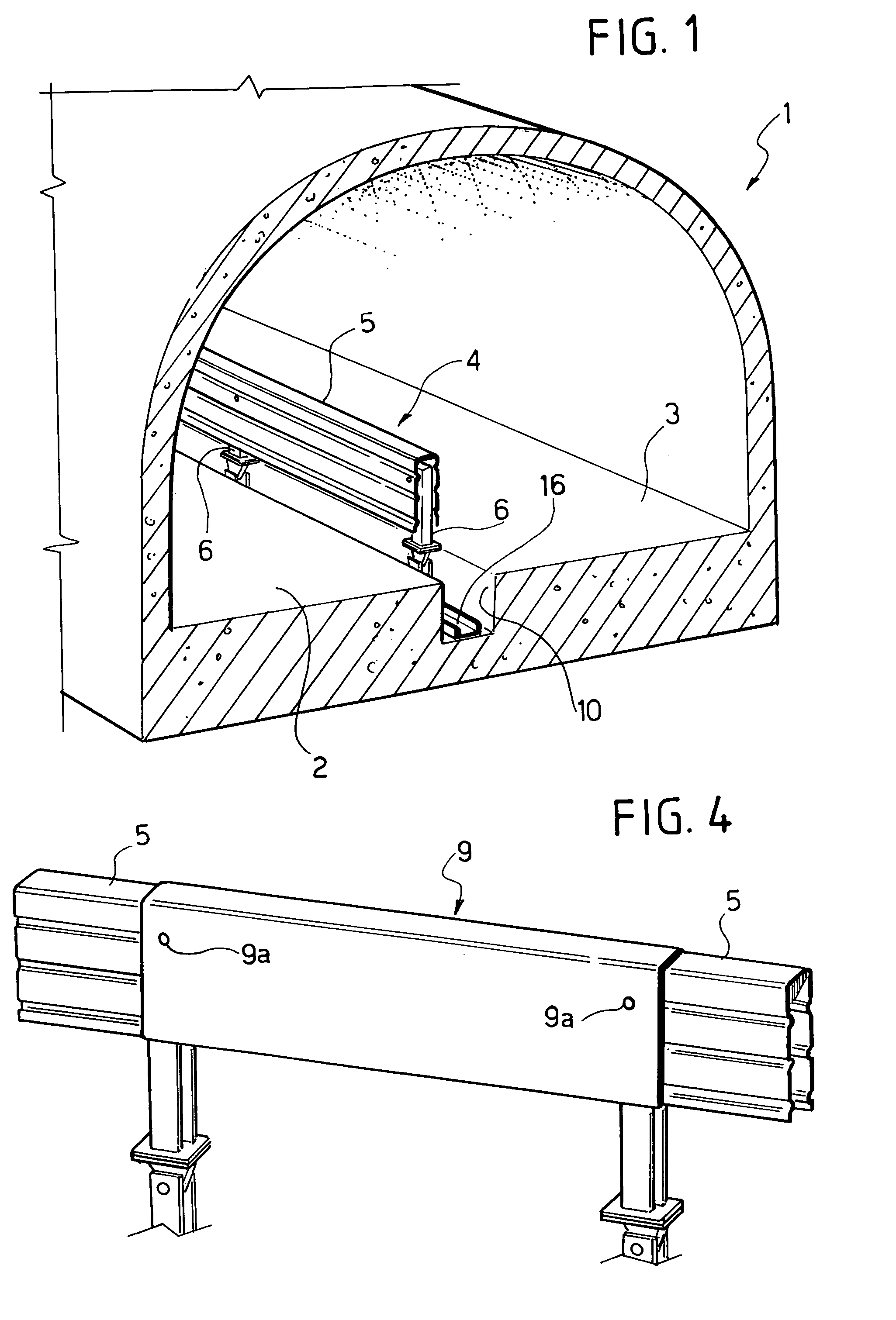
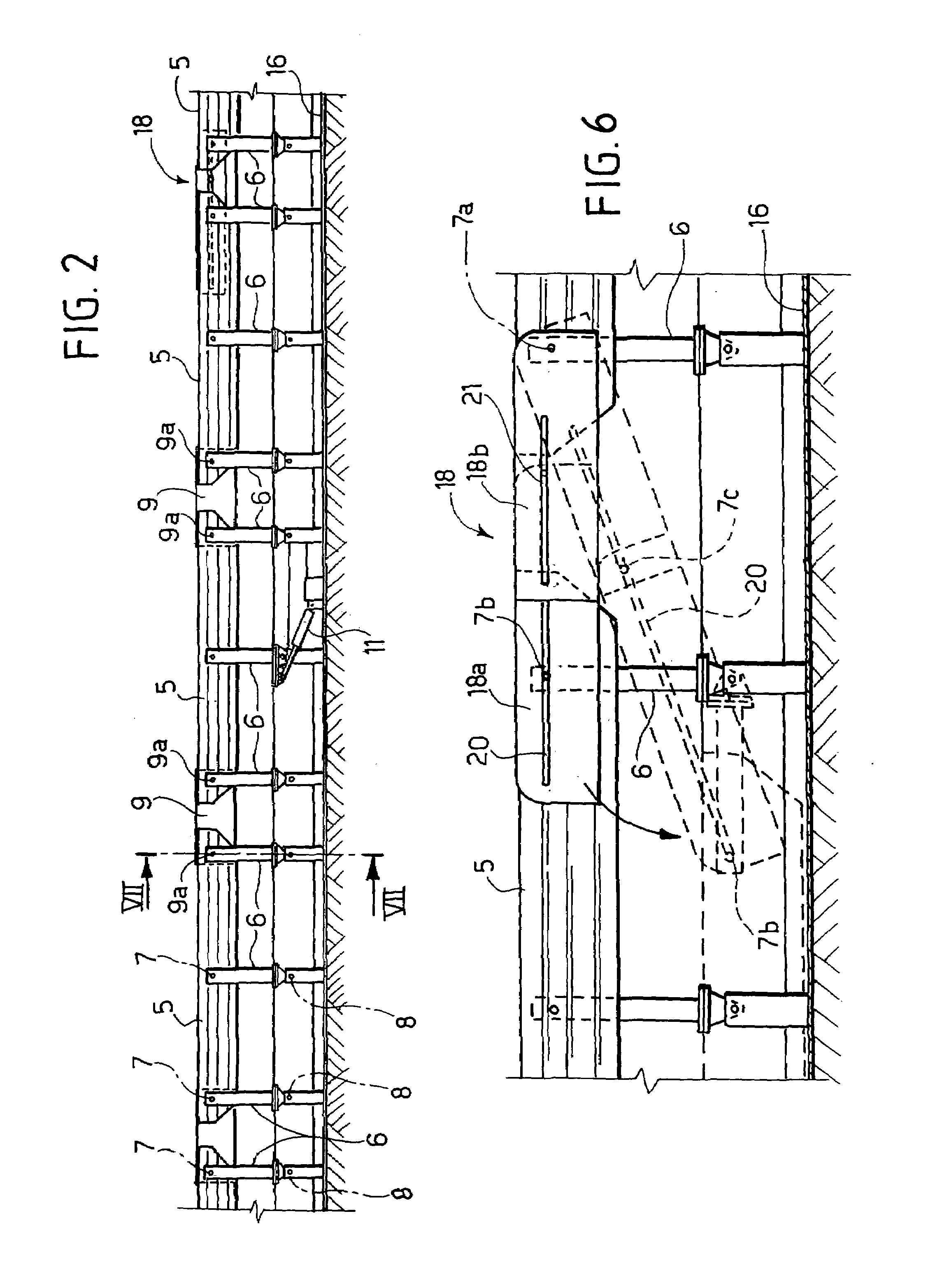
[0019]The barrier 4 comprises an aligned succession of barrier elements 5 consisting of metal channel section with reversed-U cross section and undulations for stiffening, if so required, the said barrier elements being each carried by a set of three supporting columns 6. Each column 6 has one end articulated in 7 (FIG. 2) to the respective barrier element 5, and the opposite end articulated in 8 to an attachment element anchored to the ground.

[0020]The barrier elements 5 are rigidly connected together in sets of a number of elements (for example, three) by connecting elements 9 consisting of reversed-U channel section, which are set on top of one other and are bolted by means of screws 9a (see FIG. 7) to the barrier elements 5. The ensemble consisting of three b...


PUM


Abstract

A safety barrier for road use comprises a barrier element which can be displaced between an operative position, above the road surface, and an inoperative position, in which it does not substantially project above the road surface. Preferably provided is a number of sets of aligned barrier elements, rigidly connected to one another, the adjacent sets being connected together by articulated connecting structures which enable one set of barrier elements to be displaced between its inoperative position and its operative position without modifying the positions of the adjacent sets. In this way, one or more stretches of the barrier can be brought into the inoperative condition, leaving the adjacent stretches of barrier in the normal operative condition.

Description

[0001]This is a National Stage Entry of Application No. PCT / IB02 / 04834 filed Nov. 19, 2002; the disclosure of which is incorporated herein by reference.BACKGROUND OF THE INVENTION[0002]The present invention relates to safety barriers for road use of the type comprising at least one barrier element and a supporting structure for supporting the barrier element, provided with means for anchoring thereof to the ground, wherein said supporting structure is movable between a first position, in which the barrier element is in an operative position above the road surface, and a second position, in which the barrier element is in an inoperative position in which it does not substantially project above the road surface, wherein in said inoperative condition the barrier element is received inside a trench formed in the road surface, wherein the supporting structure includes at least one supporting column articulated at one of its ends to a bracket for anchorage to the ground and, at the opposi...

Claims


Application Information

Patent Timeline
IPC IPC(8): E01F15/12
CPCE01F15/12
Inventor FUGANTI, ANTONIOSANDRI, SILVANOBOCHICCHIO, MARIORE FIORENTIN, STEFANOPALAZZETTI, MARIOFREDIANI, SALVATOREPUPPINI, ROBERTO
Owner CENT RICERCHE FIAT SCPA
Why Eureka
Try Eureka