
Hydraulic turbine with increased power capacities

a technology of hydroelectric turbines and power capacities, applied in conventional hydroenergy generation, motors, climate sustainability, etc., can solve the problems of increasing space, forming many hazards, and not being very fish-friendly installations, and achieve the effect of increasing power capacities

Inactive Publication Date: 2005-08-09
ALSTOM CANADA
View PDF38 Cites 17 Cited by
  • Summary
  • Abstract
  • Description
  • Claims
  • Application Information

AI Technical Summary

Benefits of technology

[0006]An object of the present invention is to provide a hydraulic turbine with increased power capacities, which can be used when refurbishing existing hydraulic turbines or in new hydroelectric installations.

Problems solved by technology

Such types of installations are often not very fish friendly due to the reduced dimensions of the water passage through the turbine, the speed of the water flow, the water pressure variations across the turbine, the shear in the water flow, etc.
The many parts of the turbine which stand in the way, like the stay vanes, the wicket gates, possible axial or radial distributors, and the runner wheel, form as many hazards for the fish.
Existing methods of increasing the power of hydraulic turbines generally consist of increasing the size of the various parts of the installations, which requires more space.
Unless spare space is readily available, the power of the existing installations cannot be increased easily in this way.

Method used


Image

  • Hydraulic turbine with increased power capacities
  • Hydraulic turbine with increased power capacities
  • Hydraulic turbine with increased power capacities

Examples


Embodiment Construction

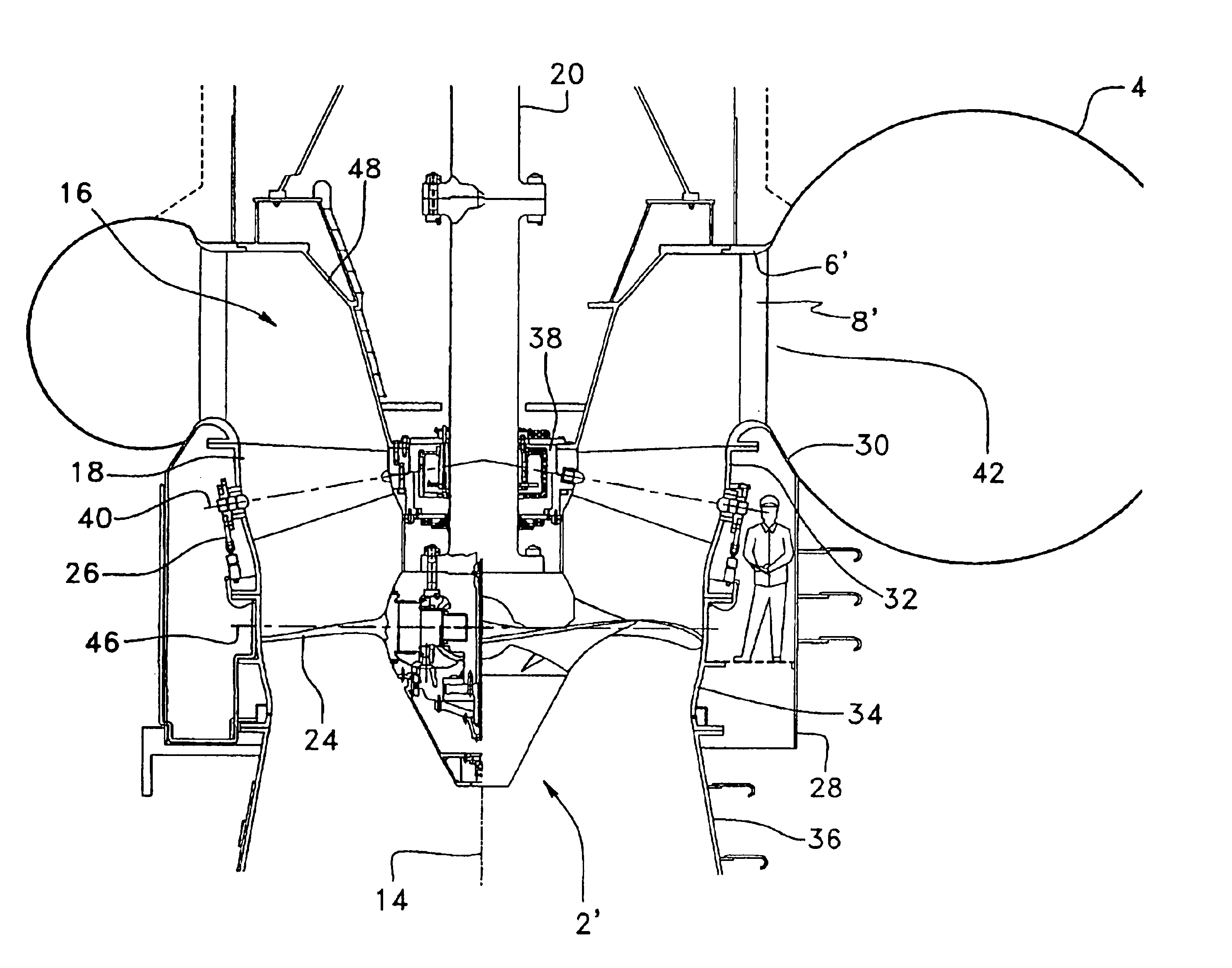
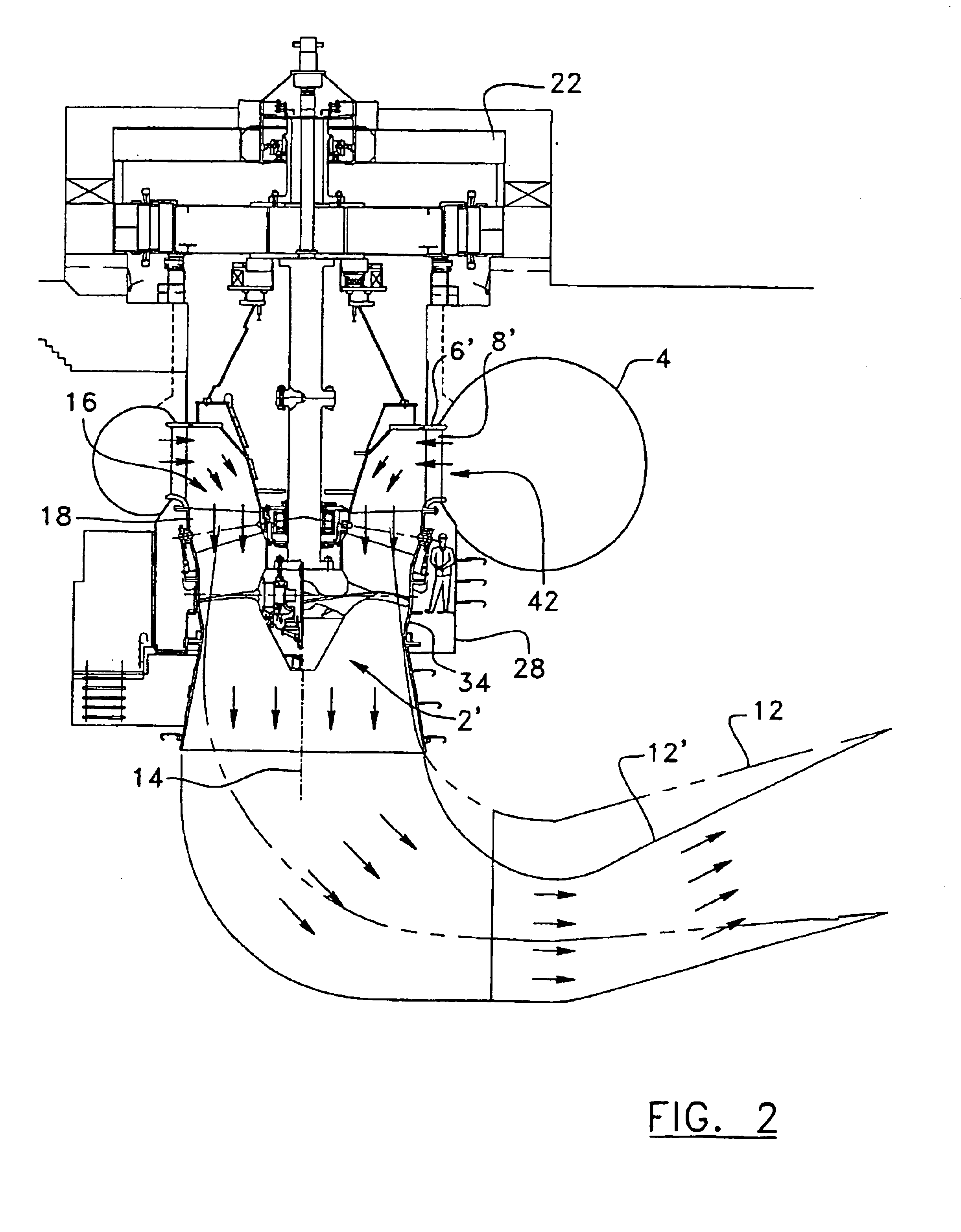
[0028]Referring to FIG. 2, there is shown a hydraulic turbine with increased power capacities according to the present invention. The new turbine is intended to be used in installations typically but not restrictively operating under 5 to 60 meters waterfalls with an optimum application zone of around 30 meters.

[0029]The replacement of a classical turbine by a turbine according to the present invention will likely increase the generated power from 50 to more than 100% while retrofitting in the former structure, thus reducing the required installation works. In the case of a new electric power plant, the turbine according to the present invention reduces the required axial space (or inter-axial space of the groups when several turbines are used).

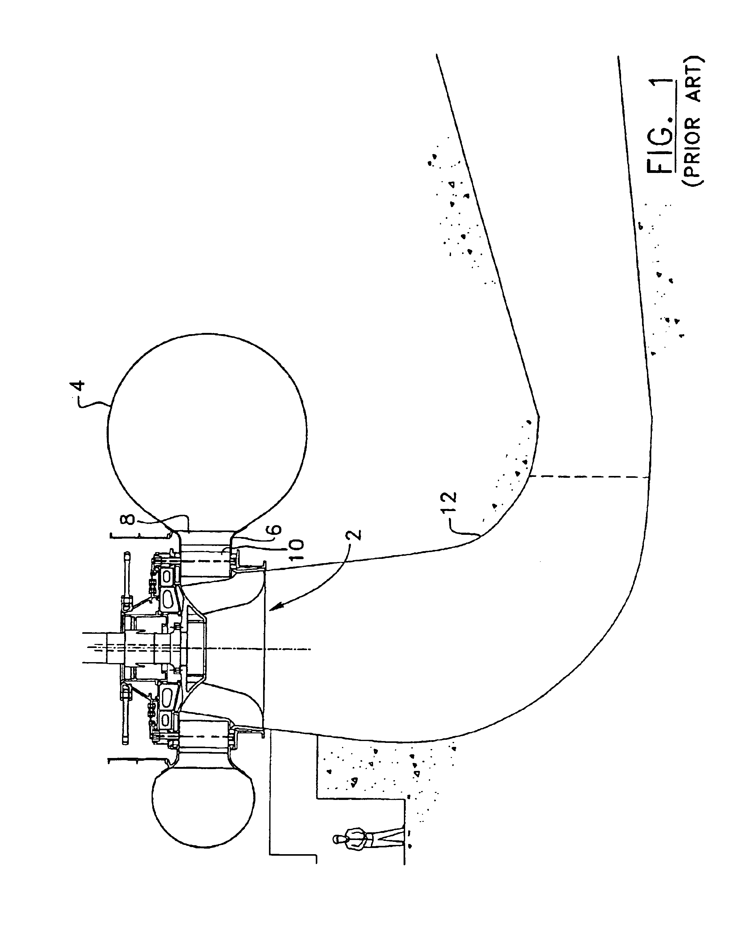
[0030]In comparison with a classical turbine as shown in FIG. 1, the turbine according to the present invention allows to increase the diameter of the runner wheel 2′ while keeping the same spiral case 4 and the same occupation space in the h...


PUM

PropertyMeasurementUnit
angleaaaaaaaaaa
power capacitiesaaaaaaaaaa
diameteraaaaaaaaaa

Abstract

A hydraulic turbine with increased power capacities for new or existing hydroelectric installations. The turbine has a larger axial runner wheel and a reshaped runner ring peripherally extending around the runner wheel. A draft tube with a larger elbow section extends on a downstream side of the runner ring. A water supply port extends around a rotation axis of the runner wheel on an upstream side of the runner ring, and is adapted to produce a centripetal water flow swirling around the rotation axis of the runner wheel. A turning passageway extends between the water supply port and the runner ring, and is adapted to guide and redirect the centripetal water flow in a substantially axial direction of the runner wheel. An axial distributor extends between the turning passageway and the runner ring.

Description

FIELD OF THE INVENTION[0001]The present invention relates to hydroelectric turbine installations, and more particularly to a hydraulic turbine with increased power capacities and a method of refurbishing an existent hydraulic turbine to increase its power capacities while being fish friendly.BACKGROUND[0002]Many existing hydroelectric installations are based on Francis turbines, as illustrated in FIG. 1. In these classical installations, the runner wheel 2 turns in the center of a spiral case 4. A stayring 6 with stay vanes 8 at the outlet of the spiral case 4 guides the water to the runner wheel 2. A radial distributor with wicket gates 10 behind the stay vanes 8 controls the water flow and distributes the water evenly around the runner wheel 2. The water passes through the runner wheel 2 and follows its course in a draft tube 12.[0003]Such types of installations are often not very fish friendly due to the reduced dimensions of the water passage through the turbine, the speed of th...

Claims


Application Information

Patent Timeline
Patent Type & Authority Patents(United States)
IPC IPC(8): F03B3/18F03B3/00F03B3/04F03B13/08F03B13/00
CPCF03B3/04F03B3/186F03B13/08Y10T29/49318Y02E10/22Y02E10/223F05B2230/80Y02E10/20Y02P70/50
Inventor SABOURIN, MICHEL
Owner ALSTOM CANADA
Learn More