Joint assembly and sealing boot

a joint assembly and sealing technology, applied in the direction of shafts, bearings, yielding couplings, etc., can solve problems such as leakage or contamination, vibration and noise, and achieve the effect of improving the boo

Inactive Publication Date: 2005-08-09
GKN AUTOMOTIVE INC
View PDF7 Cites 16 Cited by
  • Summary
  • Abstract
  • Description
  • Claims
  • Application Information

AI Technical Summary

Benefits of technology

[0015]Another advantage of the present invention is a bead design on a boot for use in a joint.
[0016]Still another advantage of the present invention is the ability to have a proper seal between a boot and cover that may have imperfections.
[0017]Other objects, features and advantages of the present invention will become apparent from the subsequent description and the appended claims, taken in conjunction with the accompanying drawings.BRIEF DESCRPTION OF THE DRAWINGS
[0018]FIG. 1 is a cross-sectional view of the sealing boot of the present invention shown affixed to a constant velocity joint.
[0019]FIG. 2 is an exploded perspective view of the sealing boot of FIG. 1 and an inner race of the constant velocity joint.
[0020]FIG. 3 is a cross sectional view of the constant velocity joint of FIGS. 1 and 2.

Problems solved by technology

Plunging tripod universal joints allow their respective interconnection shafts to change length during operation without the use of splines which provoke significant reaction forces thereby resulting in a source of vibration and noise.
Prior art seals may have imperfections between the cover and boot which may lead to leakage or contamination.

Method used


Image

  • Joint assembly and sealing boot
  • Joint assembly and sealing boot
  • Joint assembly and sealing boot

Examples


Embodiment Construction

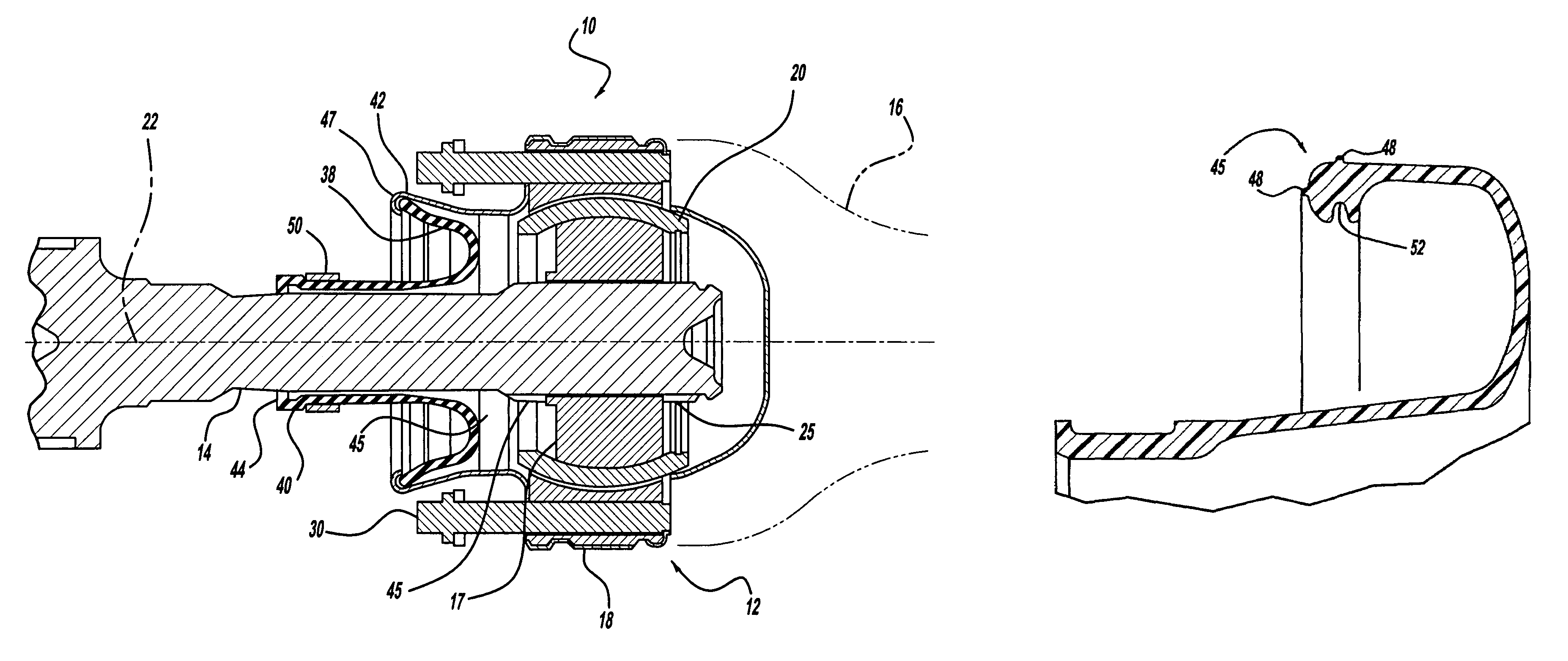
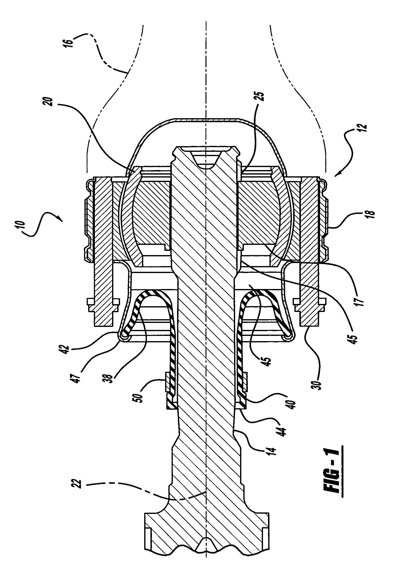
[0024]Referring to the figures, there is shown a constant velocity joint and shaft assembly 10 according to the invention. The assembly 10 includes a constant velocity joint 12 for transmitting torque between a first shaft 14 and another component such as a second shaft 16. One of the shafts 14 or 16 may be a drive shaft such as a propeller shaft. It should be noted that shafts 14 or 16 may also be side shafts in other contemplated embodiments. The joint 12 includes a first joint part such as an inner race 17, a second joint part such as an outer race 18, and a ball cage 20 disposed in an annular space between the races 17 and 18. While the joint 12 is configured to operate through a wide range of angles, FIG. 1 shows the races 17 and 18 and ball cage 20 aligned along a common central axis 22.

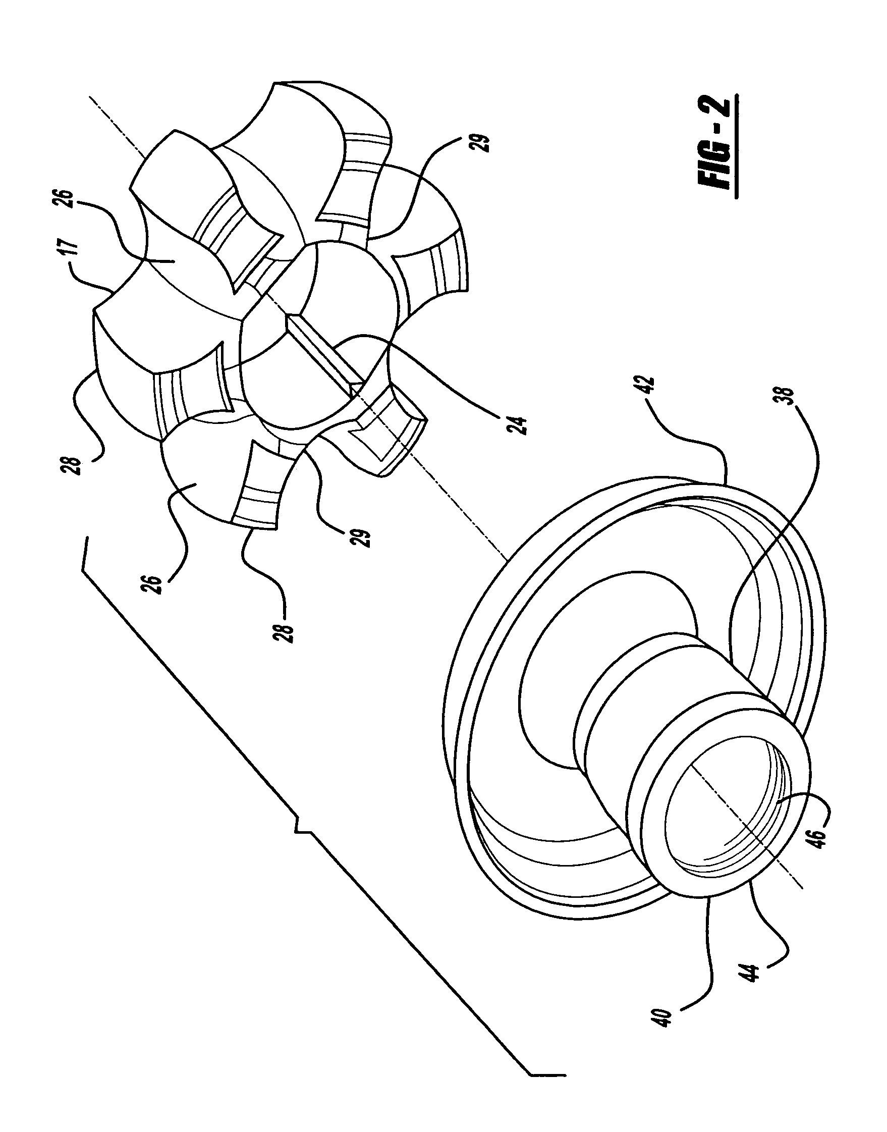
[0025]As shown more particularly in FIGS. 2–3, the inner race 17 is slidably connected to the first shaft 14 in any suitable manner. For example, the inner race 17 may be provided with a spline...


PUM


Abstract

A joint sealing boot comprises a first end affixable to a shaft, and a second end affixable to a boot cover, the second end having a sealing area including at least one sealing bead for sealing the joint and preventing grease egress and contamination ingress.

Description

TECHNICAL FIELD[0001]The present invention relates to an improved sealing solution for a propshaft joint boot.BACKGROUND ART[0002]There are generally four (4) main types of automotive drive line systems. More specifically, there exists a full-time front wheel drive system, a full-time rear wheel drive system, a part-time four wheel drive system, and an all-wheel drive system. Most commonly, the systems are distinguished by the delivery of power to different combinations of drive wheels, i.e., front drive wheels, rear drive wheels or some combination thereof. In addition to delivering power to a particular combination of drive wheels, most drive systems permit the respectively driven wheels to rotate at different speeds. For example, the outside wheels may rotate faster than the inside drive wheels, and the front drive wheels normally rotate faster than the rear wheels.[0003]Drive line systems also include one or more constant velocity universal joints (e.g. plunging tripod, plunging...

Claims


Application Information

Patent Timeline
Patent Type & Authority Patents(United States)
IPC IPC(8): F16D3/00F16D3/84F16J3/00F16J3/04
CPCF16D3/845F16J3/041F16D3/223
Inventor WANG, SHEN-LING ALLENFANARA, PAUL ANTHONY
Owner GKN AUTOMOTIVE INC
Why Eureka
Try Eureka