Rotary electric machine having stator rotation-restricting bolt

a technology of rotating restriction bolt and rotary electric machine, which is applied in the direction of dynamo-electric machines, synchronous generators, magnetic circuit shapes/forms/construction, etc., can solve the problems of reducing electric power, difficult to accurately fit the taper pin, and difficult to remove the taper pin, so as to reduce electric power loss, increase magnetic resistance, and reduce the effect of nois

Inactive Publication Date: 2005-08-09
DENSO CORP
View PDF8 Cites 4 Cited by
  • Summary
  • Abstract
  • Description
  • Claims
  • Application Information

AI Technical Summary

Benefits of technology

[0007]It is an object of the present invention to tightly fix a stator core for restricting turning caused by a rotating force generated by a rotor.
[0008]It is another object of the present invention to restrict electric power loss due to an increase in magnetic resistance and an increase in magnetic noise due to deformation of the stator core.
[0009]According to one aspect of the present invention, an intermediate member, which is softer than a bolt, is provided at one axial end portion of a stator core. A flange or a washer of the bolt readily cuts into the intermediate member by an axial force generated when fastening the bolt. Therefore, the intermediate member works as a detent so that the stator core is tightly fixed to a housing. Thus, it is not necessary to provide a groove on the stator core and hence an electric power loss due to magnetic resistance is minimized. Moreover, since the intermediate member is deformed instead of the stator core, the magnetic noise due to the deformation of the stator core is suppressed. Further, the stator core is tightly fixed to the housing not to turn by only fastening the bolt into the housing. Thus, mounting-workability is improved. Further, the stator core is detachable from the housing by only removing the bolt so that it is easy to repair components.
[0010]According to another aspect of the present invention, a cavity is provided at an axial end portion of a stator core to receive a head of a bolt therein so that the stator core is tightly fixed to the housing and the stator core is restricted from turning. Cut portions of the stator core are fewer so that the electric power loss due to increased magnetic resistance is minimized. Further, the stator core is not deformed so that the magnetic noise due to the deformation of the stator core is minimized.

Problems solved by technology

Moreover, electric power is decreased due to magnetic resistance caused by the grooves of the stator core.
High quality is required to the taper pin, and it is difficult to fit the taper pin accurately.
Further, once the taper pin is fit, it is difficult to remove the taper pin and repair is difficult.

Method used


Image

  • Rotary electric machine having stator rotation-restricting bolt
  • Rotary electric machine having stator rotation-restricting bolt
  • Rotary electric machine having stator rotation-restricting bolt

Examples


first embodiment

[0017][First Embodiment]

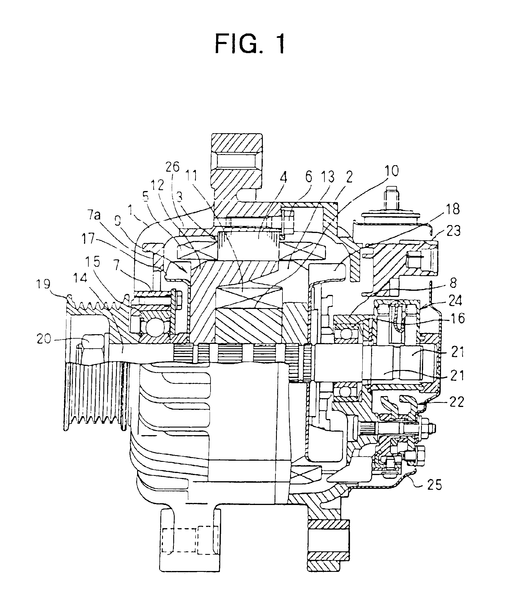
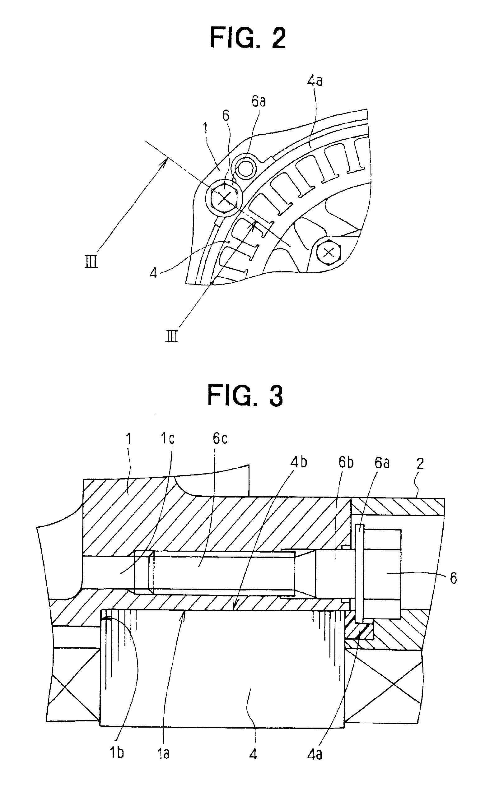
[0018]Referring to FIG. 1 showing an a.c. generator for a vehicle, a front housing 1 and a rear housing 2 are formed into a cup shape by aluminum die-casting. The front housing 1 and the rear housing 2 are fixed to each other by press-contacting openings thereof. A stator 3 is composed of a generally cylindrical stator core 4 made of iron sheets and stator coils 5. The stator core 4 is fixed to the front housing 1 with a metal bolt 6. Bearing boxes 7 and 8 are respectively integrated in the front housing 1 and the rear housing 2. Bearing box7 includes a support rib 7a extending in a radial direct to connect the bearing box 7 to a cylindrical portion 1a of the housing 1 where the stator core 4 is disposed. The cylindrical portion 1a has a thick portion 26 having a radial thickness that is thicker than another portion of the cylindrical portion 1a.

[0019]A rotor 9 includes a coil bobbin 10, an excitation coil 11, pole cores 12, 13, a rotor shaft 14 and the like...

second embodiment

[0026][Second Embodiment]

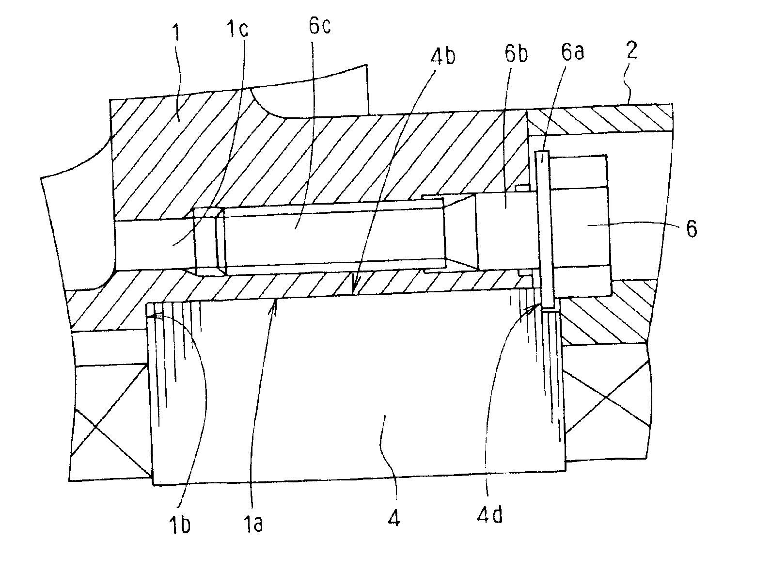
[0027]In a second embodiment, a cavity or recess 4d is provided at a radially outermost axial end portion of the stator core 4 so that the flange 6a of the bolt 6 is received therein and directly presses the stator core 4 in the axial direction. The cavity 4d works as a detent to restrict the stator core 4 from turning when the rotor 9 rotates.

[0028]In the second embodiment, the cavity 4d is formed into a semicircular shape to match the flange 6a of the bolt 6. However, the cavity 4d may have any shapes to work as a detent, such as a triangle. Moreover, similar to the first embodiment, a plurality of bolts may be used on a circular periphery having a slightly larger diameter than that of the outer periphery of the stator core 4, at substantially equal angular intervals, in order to tightly fix the stator core 4 and the front housing 1.


PUM


Abstract

A stator core is fixed to a housing by pressing an axial end portion thereof in an axial direction by a flange or a washer of a bolt. An intermediate member, which is softer than the flange or the washer of the bolt, is provided at a contact portion between the flange or the washer and the axial end portion of the stator core. The stator core may have a cavity to directly receive the flange or washer of the bolt in place of the intermediate member.

Description

CROSS-REFERENCE TO RELATED APPLICATION[0001]This application is based upon and claims the benefit of Japanese Patent Application No. 2000-258896 filed on Aug. 29, 2000, the contents of which are incorporated herein by reference.BACKGROUND OF THE INVENTION[0002]The present invention relates to a rotary electric machine, such as an electric power generator and an electric motor, fixing a stator core therein.[0003]In rotary electric machines, a stator core fixed to a housing turns by a rotating force generated by a rotor. Therefore, it is necessary to tightly fix the stator core not to turn in the housing as proposed in JP-A-9-172747 and JP-U-5-15647.[0004]JP-A-9-172747 uses bolts having a tapered engaging portion. The bolts are threaded into grooves provided on an outer periphery of the stator core in an axial direction. The tapered engaging portion of the bolt is fit in the groove, and an axial force generated by fastening the bolt is decreased. Therefore, the stator core is not tigh...

Claims


Application Information

Patent Timeline
Patent Type & Authority Patents(United States)
IPC IPC(8): H02K5/15H02K1/18H02K15/02H02K19/22
CPCH02K5/15
Inventor OKAWA, GOROKU
Owner DENSO CORP
Why Eureka
Try Eureka