
Apparatus and method for a communication device

a communication device and apparatus technology, applied in the structure of loop antennas, radiating elements, instruments, etc., can solve the problems of reducing sensitivity, limiting the use of data carriers, and difficulty in sending/receiving, so as to achieve high specific magnetic permeability, reduce the attenuation of communicable magnetic flux, and reduce the effect of transmission loss

Inactive Publication Date: 2005-08-09
HANEX CO LTD
View PDF8 Cites 237 Cited by
  • Summary
  • Abstract
  • Description
  • Claims
  • Application Information

AI Technical Summary

Benefits of technology

[0024]This invention serves to solve the foregoing problems and aims to provide a communication device, an installation structure for the communication device, a method of manufacturing the communication device, and a method of communication with the communication device in which the communication device has a sheet-like magnetic material with a high specific magnetic permeability being arranged thereto in a manner extending from a particular portion of an antenna coil of the communication device to an outer area of the antenna coil so as to exceedingly restrain a conductive material from attenuating magnetic flux and to expand communication distance even when the communication device is attached to a conductive member e.g., metal, in a closely contacting manner.
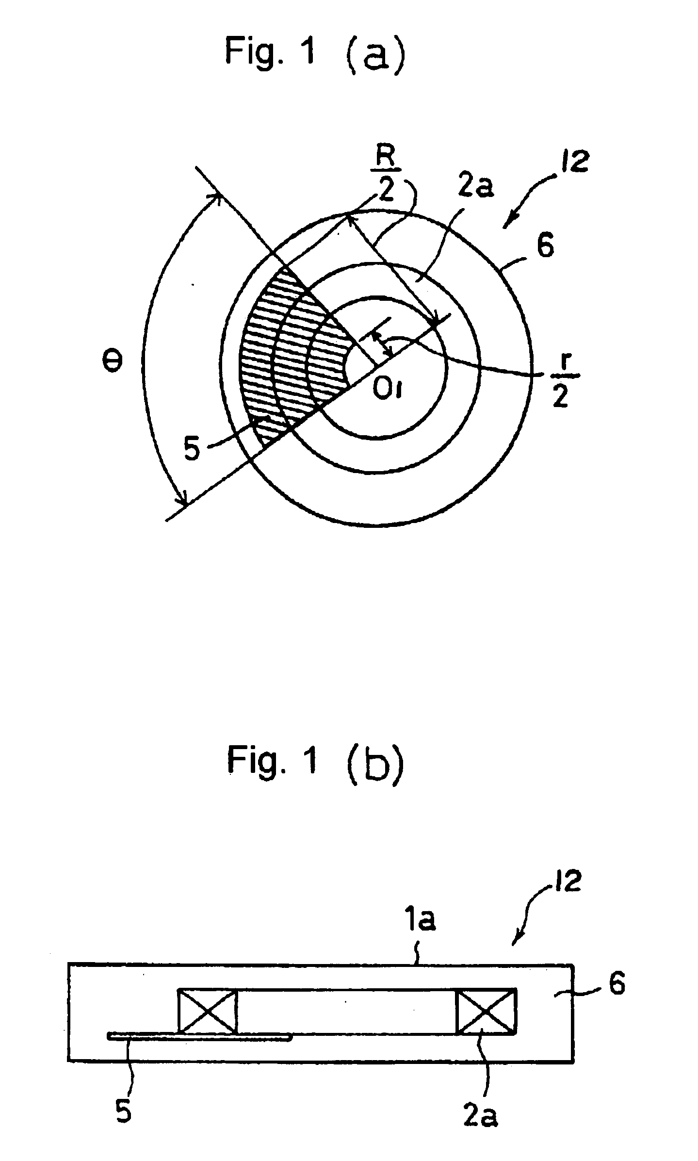
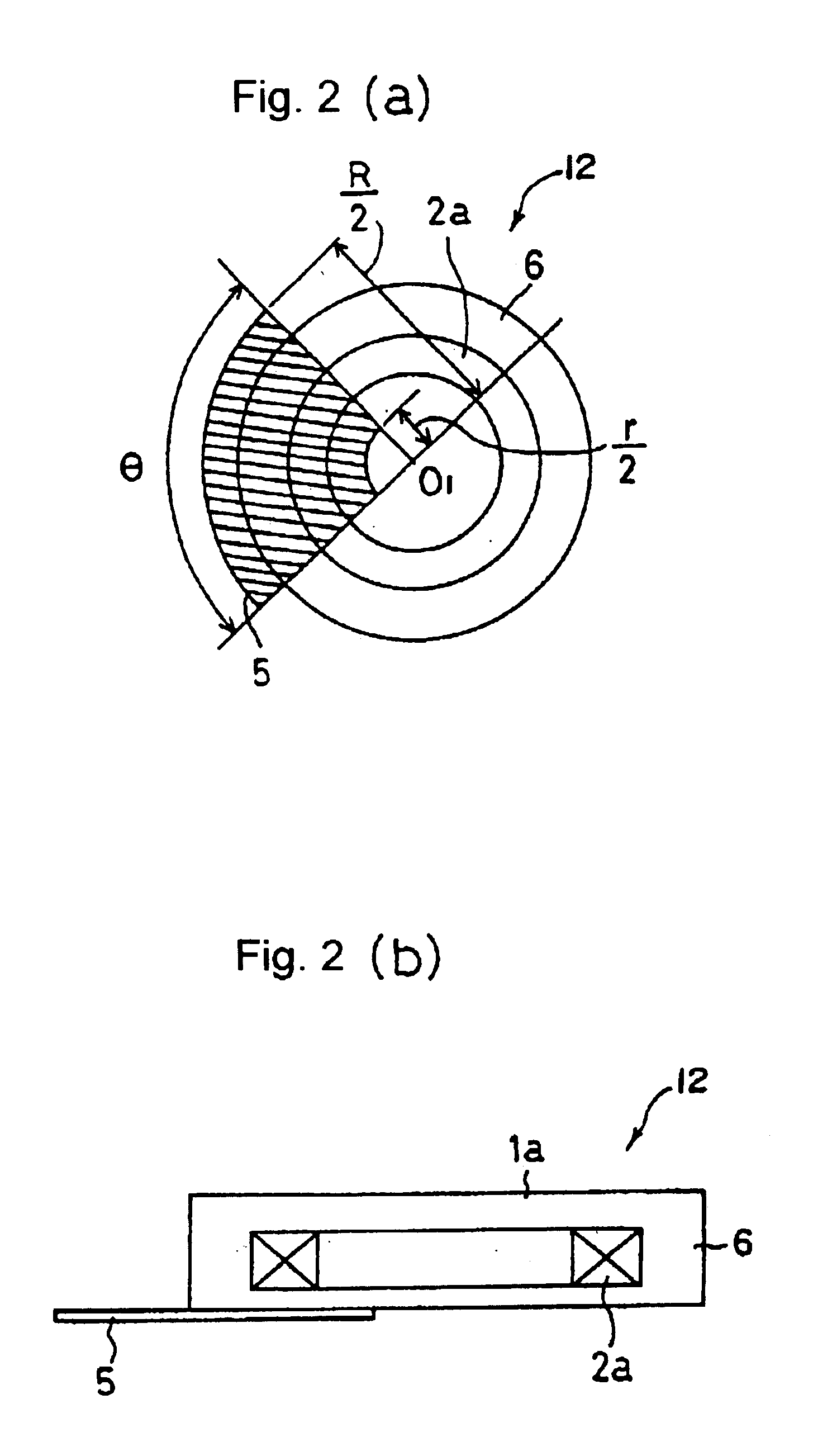
[0025]Although there are the following two types of antenna coils for a communication device, where one being a concentric disk shape (circular coil with an empty core) and the other being a cylindrical shape formed by spirally coiling a conductor to a rod-like magnetic material core, the inventor(s) of this invention found through research and experimenting that both types having a sheet-like magnetic material with a high specific magnetic permeability (hereinafter simply referred as “sheet-like magnetic material”) arranged thereto in a manner extending from a magnetic flux-generating portion (main portion for generating magnetic flux when applying an electrical current to the antenna coil based on Ampere's law) to an outer area of the antenna coil can restrain a conductive material arranged closely contacting to the communication device (e.g., an RFID tag) from reducing sensitivity and can also heighten the directivity in the extending direction and expand communication distance.

Problems solved by technology

However, in a case such as attaching a data carrier such as an RFID tag upon a product for product management, the use of the data carrier would be restricted if the communication distance is short.
The eddy current produces a magnetic flux opposing to a magnetic flux purposed for sending / receiving and thereby attenuates the magnetic flux purposed for sending / receiving and causes difficulty in sending / receiving.
However, through the findings of the inventors of this invention, even if the sending / receiving sensitivity of the RFID tag is slightly improved compared to a situation where the sheet-like magnetic material is not arranged entirely across the antenna coil, there is not much difference from a practical aspect; in some cases, a closed loop which passes through the sheet-like magnetic material is created to adversely result in decline of sensitivity.
However, with the foregoing method proposed in Japanese Patent Publication No.2000-48152, manufacturing is difficult and laborious since the sheet-like magnetic material is required to be inserted to the antenna coil 2a.

Method used


Image

  • Apparatus and method for a communication device
  • Apparatus and method for a communication device
  • Apparatus and method for a communication device

Examples


Embodiment Construction

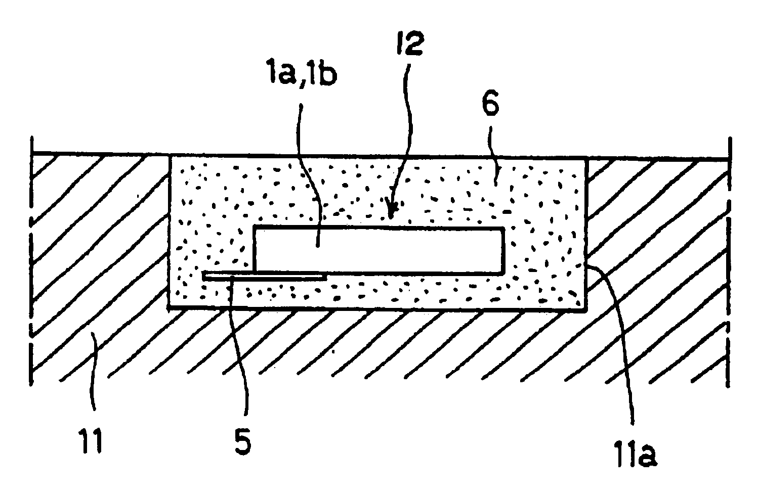
[0107]An embodiment of this invention regarding a communication device and an installment structure of the communication device, a manufacturing method of the communication device and an communication method with the communication device will hereinafter be described in detail with reference to the drawings. As one example of a proposed structure of a communication device 12, a structure of an RFID tag 1a having a flat concentric disk-shaped antenna coil 2a will hereinafter be described with reference to FIG. 1 through FIG. 4. The RFID tag 1a preferably applicable to this embodiment relate both to those of electromagnetic coupling type and electromagnetic induction type although the description below specifically deals with the latter type.

[0108]The RFID tag 1a shown in FIG. 1 through FIG. 3 is one example of a communication device 12 for communicating with electromagnetic wave by using the antenna coil 2a; the RFID tag 1a has a flat concentric disk-shaped antenna coil 2a and a semi...


PUM


Abstract

This invention aims to provide a communication device, installation structure for the communication device, a method of manufacturing the communication device, and a method of communication with the communication device in which the communication device is able to exceedingly restain a conductive material from attenuating magnetic flux and to expand communication distance even when the communication device is attached to a conductive member e.g., metal, in a closely contacting manner.This invention has a sheet-like amorphous magnetic material being arranged in a manner extending from a magnetic flux generating portion of a concentric disk-shaped antenna coil of an RFID tag serving as the communication device to an outer area of the antenna coil.

Description

TECHNICAL FIELD[0001]This invention relates to a communication device using an antenna coil for communications by electromagnetic wave, an installation structure for the communication device, a method of manufacturing the communication device, and a communication method with the communication device.[0002]The entire disclosure of Japanese patent application No.2001-3403 filed on Jan. 11, 2001, No.2001-124010 filed on Apr. 23, 2001 and No.2001-139044 filed on May 9, 2001, including the specification, claims, accompanying drawings and abstract of the disclosure is incorporated herein by reference in its entirety, in order to claim foreign priority right.BACKGROUND ART[0003]RFID tags (Radio Frequency-IDentification TAG) having an antenna coil and a control device such as an IC circuit, or data carriers (child) such as non-contact type IC cards are widely used in various fields to serve as communication devices communicating by electromagnetic wave, in which the communication devices co...

Claims


Application Information

Patent Timeline
IPC IPC(8): G06K19/077G06K19/07H01Q1/22H01Q7/00H01Q7/08
CPCG06K19/0723G06K19/07749G06K19/07771H01Q1/22H01Q1/2225H01Q7/00H01Q7/08H01Q7/06
Inventor SENBA, FUJIOHYODO, NAKAMAROSAKANE, TETSUSHIFUJII, JUNUCHIYAMA, TOMOKIKIDA, SHIGERU
Owner HANEX CO LTD
Learn More