Eureka AIR delivers breakthrough ideas for toughest innovation challenges, trusted by R&D personnel around the world.

Plasma display apparatus having a driver protecting portion

Inactive Publication Date: 2005-08-09
PANASONIC CORP
View PDF7 Cites 9 Cited by
  • Summary
  • Abstract
  • Description
  • Claims
  • Application Information

AI Technical Summary

Benefits of technology

[0014]The invention has been made to solve the problems mentioned above and it is an object of the invention to provide a plasma display apparatus which can certainly prevent an excessive power loss of a driver for driving electrodes of a plasma display panel.

Problems solved by technology

Since the various driving pulses as mentioned above have a relatively high voltage, if the driver for generating the driving pulses operates erroneously and is short-circuited therein, a large current flows into the driver for a long period of time, so that an excessive power loss occurs continuously.
A problem, therefore, such that even if one driver in the column electrode driver is short-circuited therein and a large current flows in the driver and its influence is reflected onto the common power line, whether it is caused by the excessive current or not cannot be easily discriminated occurs.

Method used


Image

  • Plasma display apparatus having a driver protecting portion
  • Plasma display apparatus having a driver protecting portion
  • Plasma display apparatus having a driver protecting portion

Examples


Embodiment Construction

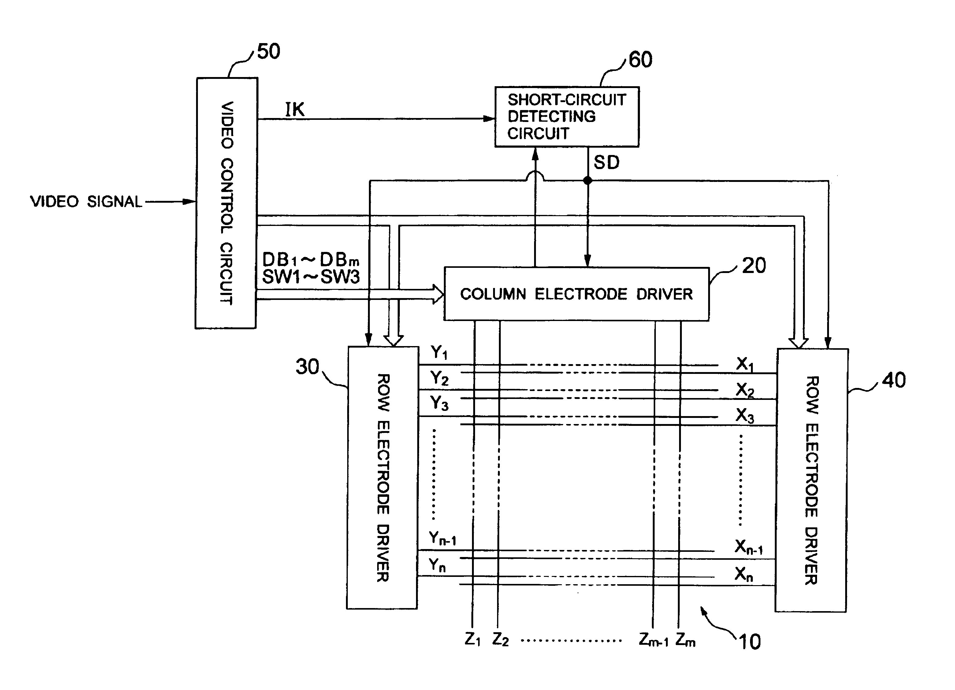
[0027]An embodiment of the invention will be described in detail hereinbelow with reference to the drawings.

[0028]FIG. 3 is a diagram showing a schematic construction of a plasma display apparatus according to the invention.

[0029]In FIG. 3, the PDP 10 as a plasma display panel comprises: the m column electrodes Z1 to Zm; and the n row electrodes X1 to Xn and n row electrodes Y1 to Yn arranged so as to cross the column electrodes, respectively. The row electrodes X1 to Xn and row electrodes Y1 to Yn construct the first display line to the nth display line in the PDP 10 by pairs of row electrodes Xi (1≦i≦n) and Yi (1≦i≦n), respectively. A discharge space filled with a discharge gas is formed between the column electrode Z and the row electrodes X and Y. A discharge cell which performs a discharge light emission in red, a discharge cell which performs a discharge light emission in green, or a discharge cell which performs a discharge light emission in blue is formed at each intersectin...


PUM


Abstract

A plasma display apparatus which can surely prevent an overcurrent flowing in a driver for driving electrodes of a plasma display panel. A power source is shut off when an internal short-circuit state of a column electrode driver is detected based on a current or an electric potential on a power line in a column electrode driver detected during a light emission sustaining period.

Description

BACKGROUND OF THE INVENTION[0001]1. Field of the Invention[0002]The present invention relates to a plasma display apparatus.[0003]2. Description of Related Art[0004]Plasma display panels are nowadays drawing attention as a type of thin-shape flat display device.[0005]FIG. 1 is a diagram schematically showing the construction of a plasma display apparatus having a plasma display panel mounted therein.[0006]In FIG. 1, a PDP 10 as a typical plasma display panel comprises: m column electrodes Z1 to Zm; and n row electrodes X1 to Xn and n row electrodes Y1 to Yn arranged so as to cross the column electrodes, respectively. The row electrodes X1 to Xn and row electrodes Y1 to Yn constitute a first display line to an nth display line in the PDP 10 by pairs of row electrodes Xi (1≦i≦n) and Yi (1≦i≦n), respectively. A discharge space filled with a discharge gas is formed between the column electrodes Z and the row electrodes X and Y. A discharge cell which performs a discharge light emission ...

Claims


Application Information

Patent Timeline
IPC IPC(8): G09G3/28G09G3/20G09G3/288G09G3/291G09G3/294G09G3/296G09G3/298
CPCG09G3/294G09G3/2965G09G3/293G09G2330/021G09G2330/04
Inventor IDE, SHIGEOIWAMI, TAKASHI
Owner PANASONIC CORP
Why Eureka
Eureka Blog
Learn More