Eureka AIR delivers breakthrough ideas for toughest innovation challenges, trusted by R&D personnel around the world.

Circuit arrangement for the reliable switching of electrical circuits

A circuit device and current loop technology, applied in the direction of output power conversion devices, circuits, electronic switches, etc., can solve the problems of limited efficiency, high turn-on current, high switching loss, etc., and achieve the effect of reducing power loss

Inactive Publication Date: 2007-03-28
WURTH ELEKTRONIK EISOS
View PDF1 Cites 0 Cited by
  • Summary
  • Abstract
  • Description
  • Claims
  • Application Information

AI Technical Summary

Problems solved by technology

However, this circuit has the disadvantage that the capacitor must be short-circuited or skip-charged when the switching device is closed, which causes high turn-on current, high switching losses, and severe welding of the switching device. Therefore, the capacitance of the capacitor is limited to very small values, which greatly limits its efficiency

Method used


Image

  • Circuit arrangement for the reliable switching of electrical circuits
  • Circuit arrangement for the reliable switching of electrical circuits
  • Circuit arrangement for the reliable switching of electrical circuits

Examples


Embodiment Construction

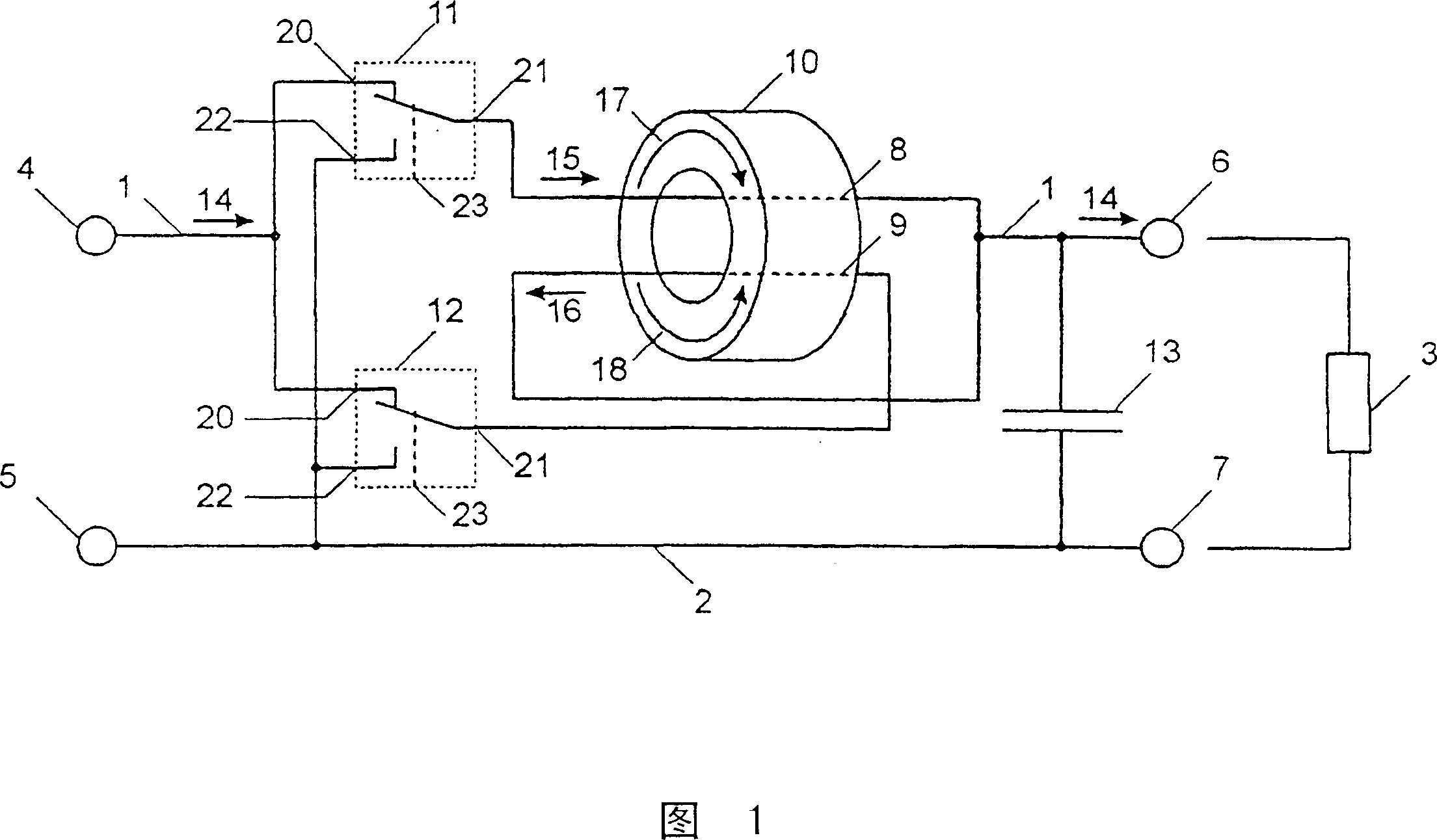
[0030] The circuit arrangement according to the invention has two longitudinal branches 1 and 2 in the lead-through to the consumer 3, two connection points 4 and 5 for connection to a voltage source, and two connections for connection to the consumer 3 Points 6 and 7.

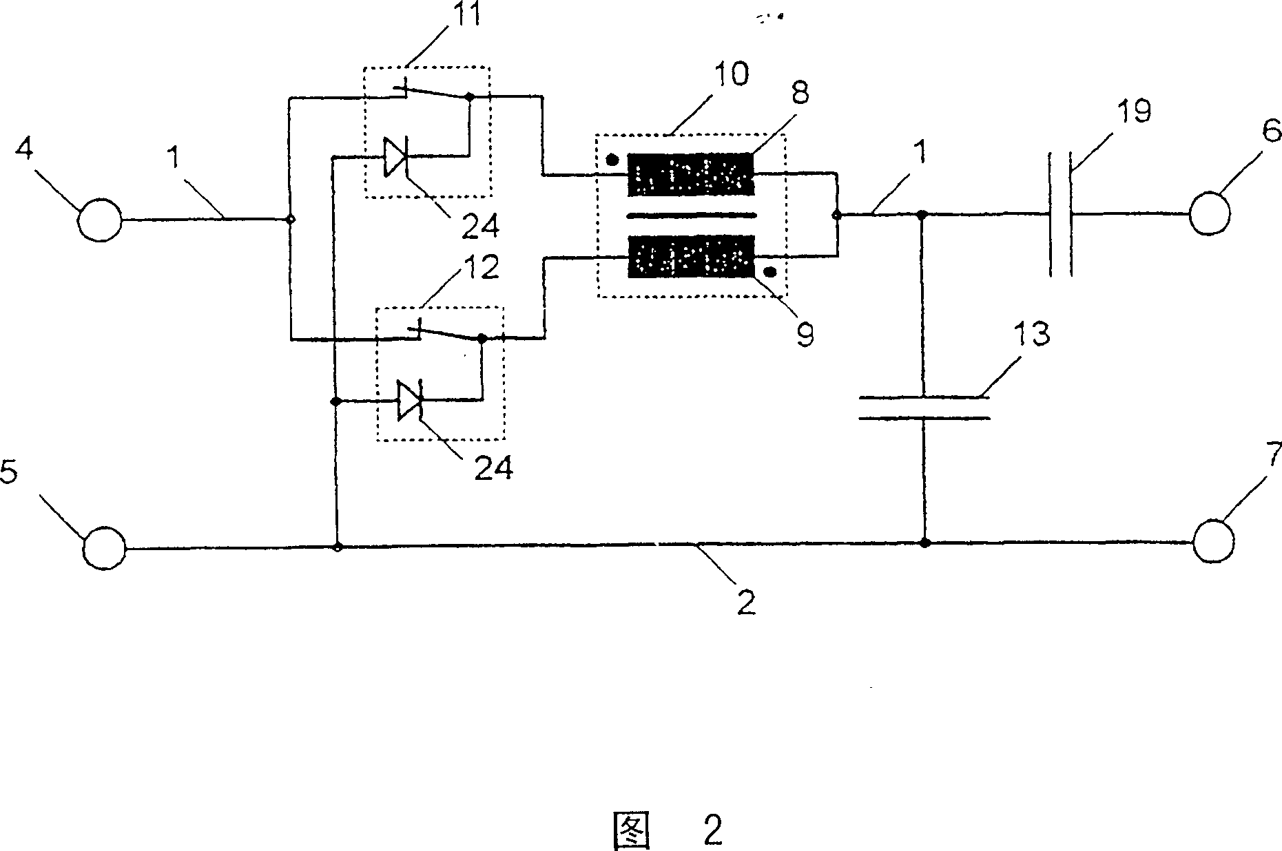
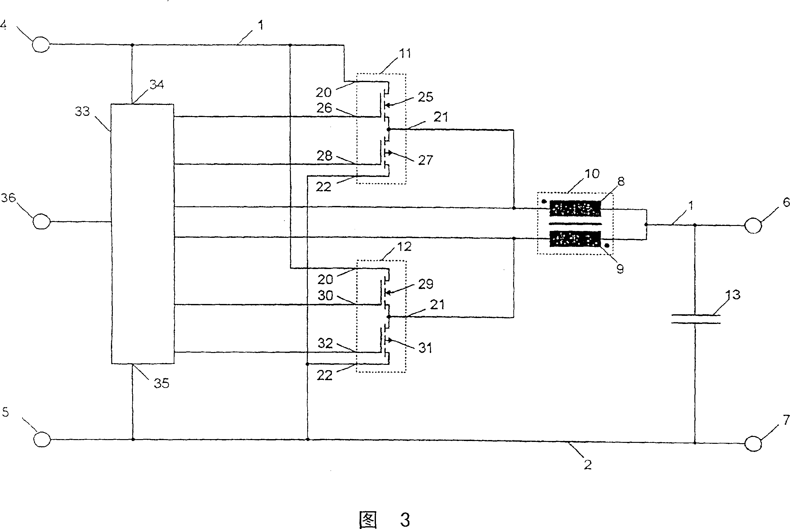
[0031] The longitudinal branch 1 is subdivided into two further longitudinal branches which each contain a winding 8 , 9 of a transformer 10 and a switching element 11 or 12 .

[0032] After the transformer 10 , the two windings 8 and 9 are connected to each other and to the connection point 6 .

[0033] Between the longitudinal branches 1 and 2 a capacitor 13 is connected in parallel to the consumer. Capacitor 13 is chosen to be very large in the case of slow-switching circuit arrangements and high consumer currents, and small in the case of fast-switching circuit arrangements, so that a line capacitance between 1 and 2 is sufficient to achieve the ideal Protective effect.

[0034] Consumer current 14 from...


PUM


Abstract

A circuit arrangement for the reliable switching of electrical circuits comprises two longitudinal branches (12), with two switching elements (11,12) arranged parallel to each other in one of the branches, the switch inputs (20) of which are connected to the input point (4,5) of the longitudinal branch and the switch outputs (21) of which are each connected to the input side of a winding (8,9) on a transformer (10).

Description

technical field [0001] To interrupt and close current circuits, not only mechanical contacts, such as sliding contacts in the brushes of rail vehicles or inverters in electric motors, fuses, but also semiconductors such as transistors, thyristors and semiconductor relays are used switch. Background technique [0002] When the current loop is interrupted, all these switching devices will experience a high self-induced voltage due to the rapid decrease of the stored inductive energy throughout the current loop. [0003] This self-induced voltage can heat and destroy semiconductor switching devices and protective circuits, cause material migration and welding on the contact surfaces, and can prevent the breaking of the current loop by forming an arc between the contact surfaces. [0004] When the current loop is closed, the capacitance present in the current loop is quickly charged, which temporarily leads to high inrush currents. [0005] This switching current causes materi...

Claims


Application Information

Patent Timeline
Patent Type & Authority Patents(China)
IPC IPC(8): H03K17/12H02M3/158H03K17/16H02M1/088H03K17/0814H03K17/687H03K17/695
CPCH02M1/088H02M3/1584H03K17/08142H03K17/122H02M3/158H03K17/12
Inventor F·弗雷
Owner WURTH ELEKTRONIK EISOS
Why Eureka
Eureka Blog
Learn More