
Method and apparatus for improving resolution of display unit

a display unit and resolution technology, applied in the field of methods and apparatus for improving the resolution of the display unit, can solve the problems of complex algorithm, relative high production cost, complex algorithm, etc., and achieve the effect of improving display resolution and image smoothness as well as display quality, and reducing production cos

Active Publication Date: 2005-08-09
WINTEK CORP
View PDF9 Cites 20 Cited by
  • Summary
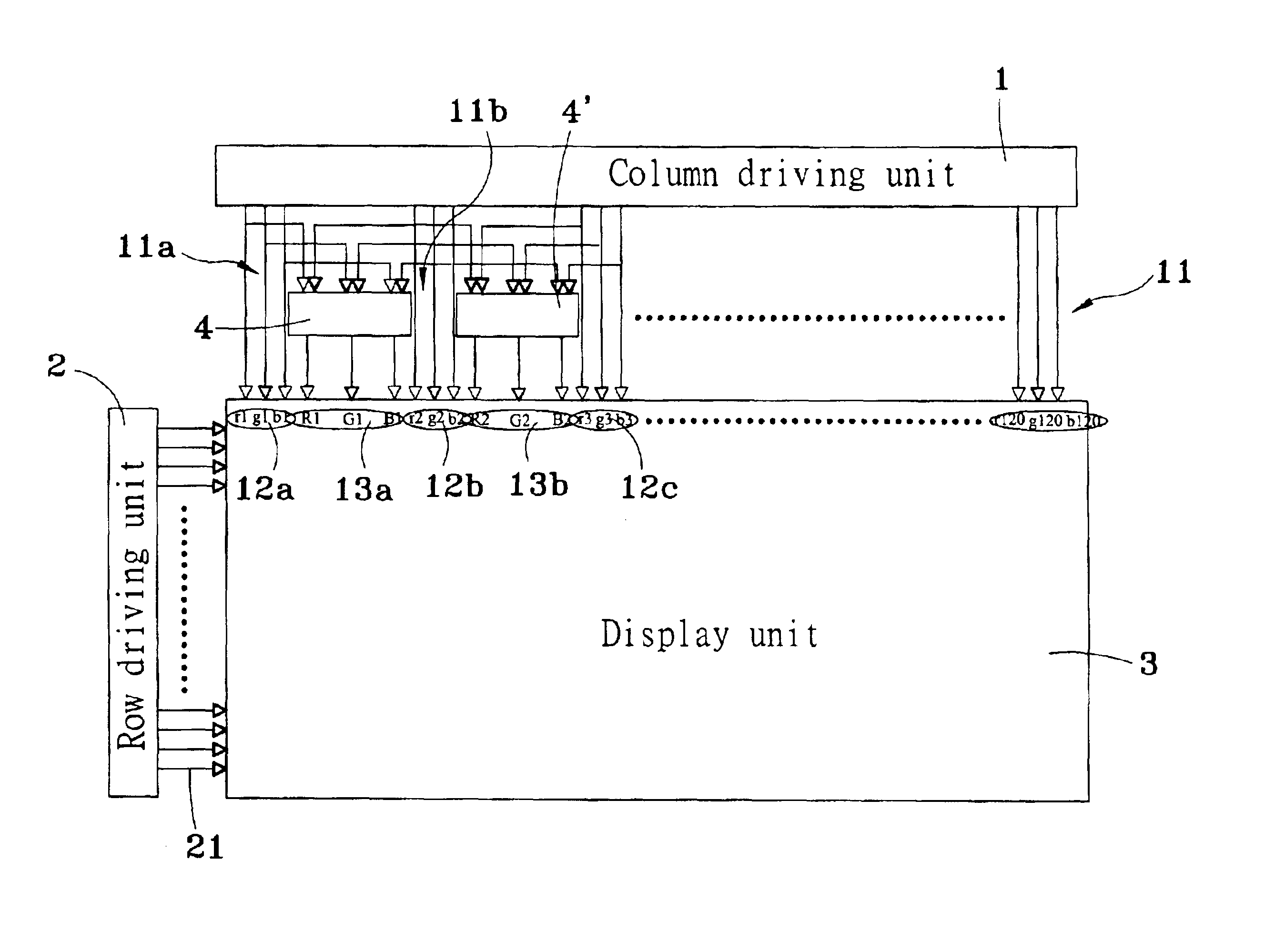
  • Abstract
  • Description
  • Claims
  • Application Information

AI Technical Summary

Benefits of technology

[0006]The principal objective of the present invention is to overcome the above shortcomings of the traditional method and device by adding a pixel between two pixels of the primitive video data to improve the display resolution and image smoothness as well as the display quality. The present invention adopts the column driving unit with smaller number of channels to lower the production cost.
[0007]To achieve the aforementioned objective, the column driving unit and the row column driving unit will drive the display unit 3, and in the meantime, the pixel processing unit will capture and add the three primitive color (r1, g1, b1, r2, g2, b2) signals of the first and second channels, and divide the sum by 2, and then generate a new three primitive color (R1, G1, B1) signal between the first and second pixels of the three primitive color (r1, g1, b1, r2, g2, b2) signals; in the meantime, another pixel processing unit will capture and add the three primitive color (r2, g2, b2, r3, g3, b3) signals of the second and third channels, and divide the sum by 2, and then generate a new three primitive color (R2, G2, B2) signal between the second and third pixels of the three primitive color (r2, g2, b2, r3, g3, b3) signals; this pixel processing method can accomplish the purpose of improving the display resolution and smoothing the image.

Problems solved by technology

Its shortcoming relies on the complexity, uneasy-to-make, and relative high production cost.
It shortcoming relies on the design has to include the color filter structure and makes the algorithm more complicated, which requires the special design of FPGA for the implementation.
Its shortcoming relies on the complicated process of the data conversion, which generally has a significant delay.

Method used


Image

  • Method and apparatus for improving resolution of display unit
  • Method and apparatus for improving resolution of display unit
  • Method and apparatus for improving resolution of display unit

Examples


Embodiment Construction

[0016]Refer to FIG. 3 for the illustrative diagram of the dot-matrix displaying structure of the present invention. In the figure, the method and apparatus of improving the resolution of the display unit of the present invention comprises the steps of using a unit between two pixels of the primitive video data matrixes to add the two pixels of the primitive video data and divide the sum, and then add the result between two pixels of the primitive video data matrix to improve the video smoothness and the display resolution; in the meantime, a column driving apparatus with less channels is chosen to lower the production cost.

[0017]To achieve the aforementioned objectives, the present invention adopts a method of using the pixels of the primitive image data matrix M(RGB)×N (where M is column, and N is row) and the desired pixel displaying to the dot matrix display unit is P(RGB)×N (where P is column, and N is row), wherein P>=M, 3×P−3×M=Q (increase number of channels is needed), and se...


PUM


Abstract

A method and apparatus for enhancing the resolution of a display unit by adding any one of the two-channels of the three primitive color (r1, g1, b1, r2, g2, and b2) signals output from the column driving unit and dividing the sum by 2, and generating a new channel between the two channels. Such channel outputs a new three primitive color (R1, G1, B1) signal. These three primitive colors are also located between the two pixels of the primitive image data matrix to improve the display resolution and image smoothness and to enhance the display quality by less channel of the column driving unit.

Description

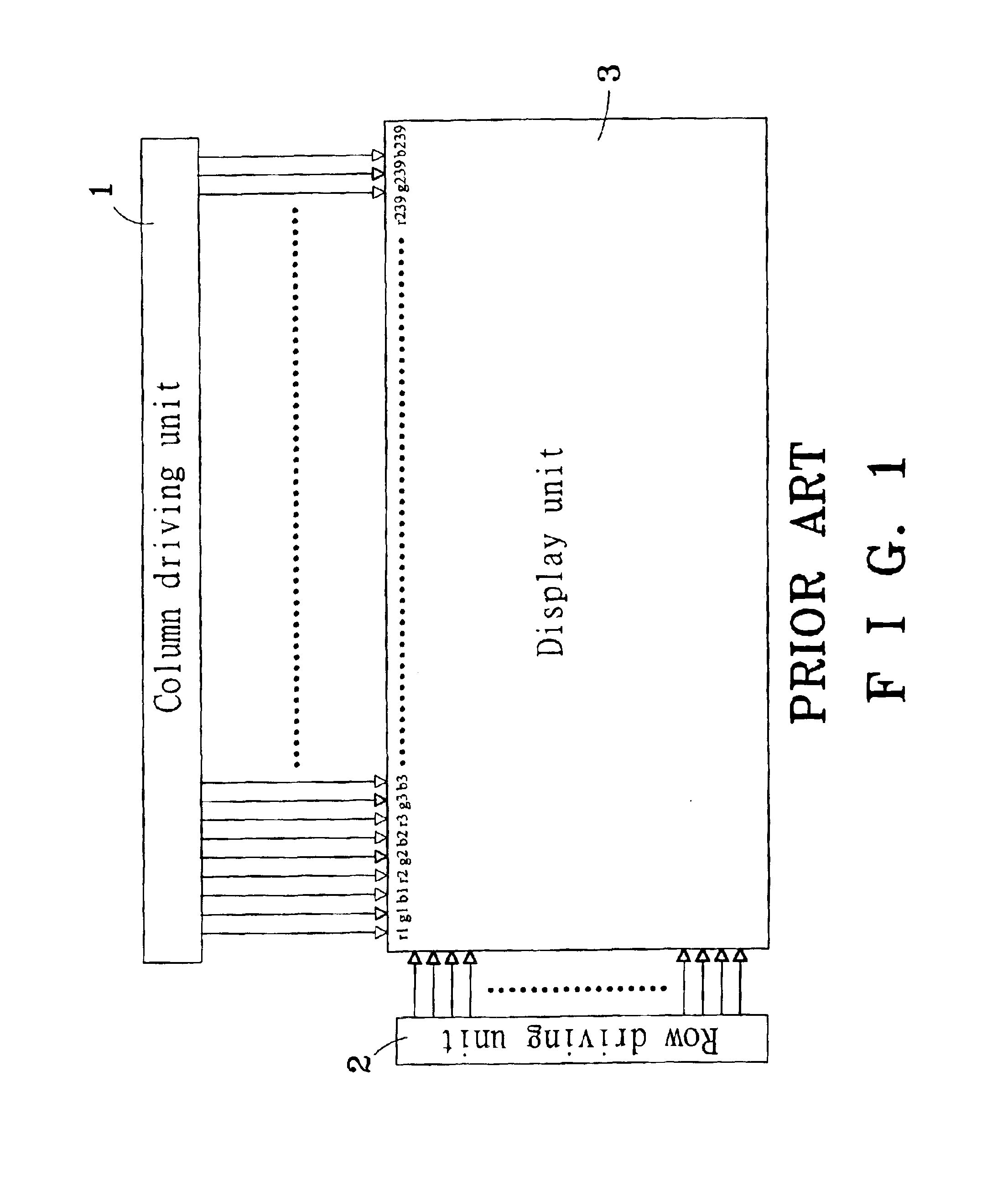
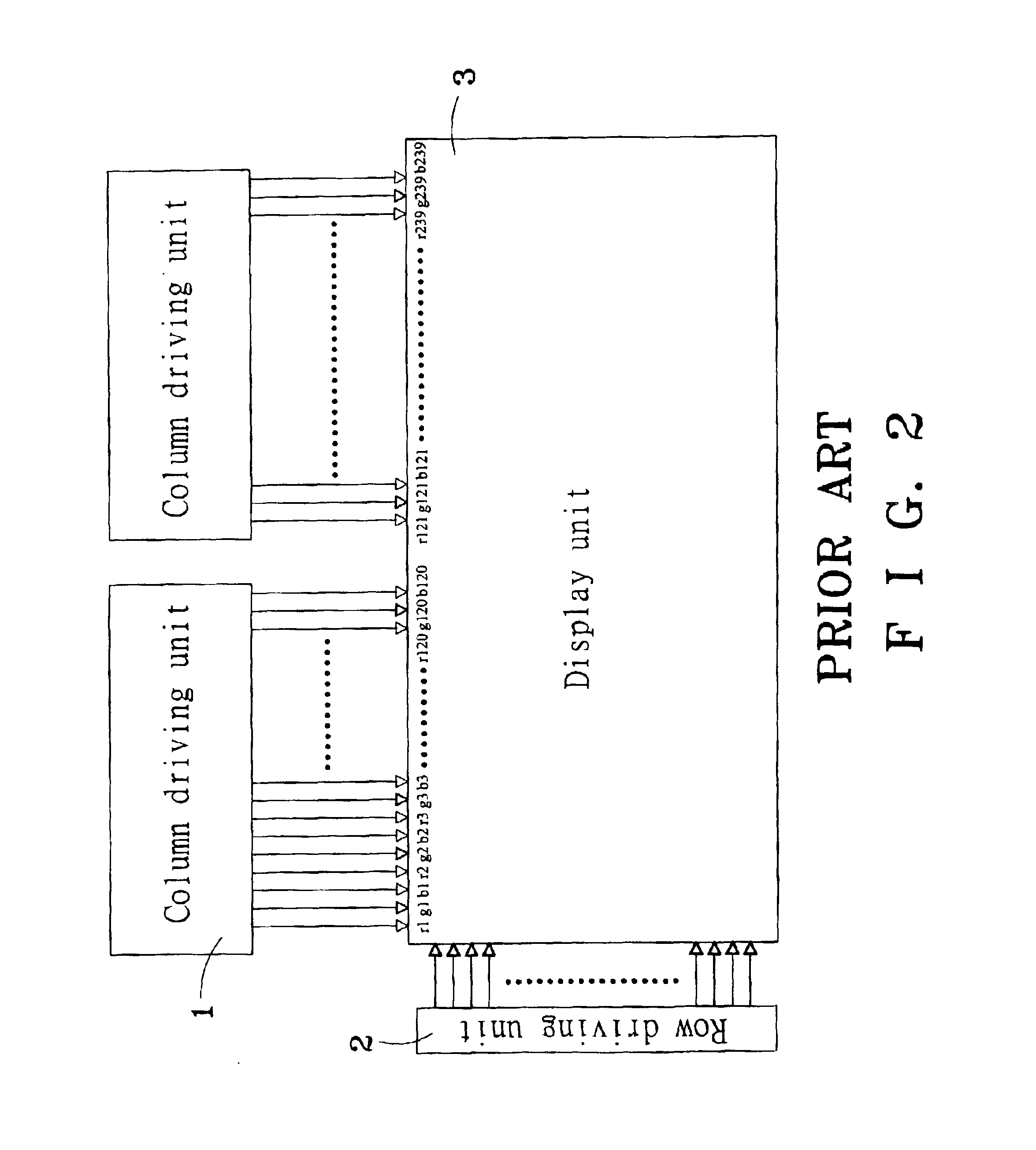
FIELD OF INVENTION[0001]The invention relates to a method and apparatus for improving resolution of a display unit, more particularly to a method and apparatus for improving display resolution, image smoothness, and display quality.BACKGROUND OF THE INVENTION[0002]It is known that the present display driving method makes use of a column driving unit and a row driving unit to drive the display device as shown in FIGS. 1 and 2. If the display unit allows the displayed graphics to have high-resolution pixels, the designer will adopt a piece of column driving unit 1 with a high channel number of 239 (RGB)=239×3, and a piece of row driving unit 2 with a channel number of 160 to drive a 239 (RGB)×160 matrix display unit 3 as shown in FIG. 1, or use a multiple pieces of column driving units 1 with a channel number of 120 (RGB)=120×3, and a piece of row driving unit 2 with a channel number of 160 to drive a 239 (RGB)×160 matrix display unit 3, and thus will cause an increase of production c...

Claims


Application Information

Patent Timeline
IPC IPC(8): G09G3/20
CPCG09G3/20G09G3/2003G09G2300/0804G09G2310/0275G09G2340/0407
Inventor LAI, CHIH-CHANG
Owner WINTEK CORP
Learn More