
Support structure of a magnetic head and magnetic card reader

a support structure and magnetic head technology, applied in the direction of maintaining the alignment of the head carrier, recording information storage, instruments, etc., can solve the problems of difficult to form a swing type magnetic head structure body into a unit, the magnetic head is difficult to easily attach and detach, etc., to achieve the effect of easy attachment and detachmen

Inactive Publication Date: 2005-08-09
HITACHI CHANNEL SOLUTIONS CORP
View PDF4 Cites 7 Cited by
  • Summary
  • Abstract
  • Description
  • Claims
  • Application Information

AI Technical Summary

Benefits of technology

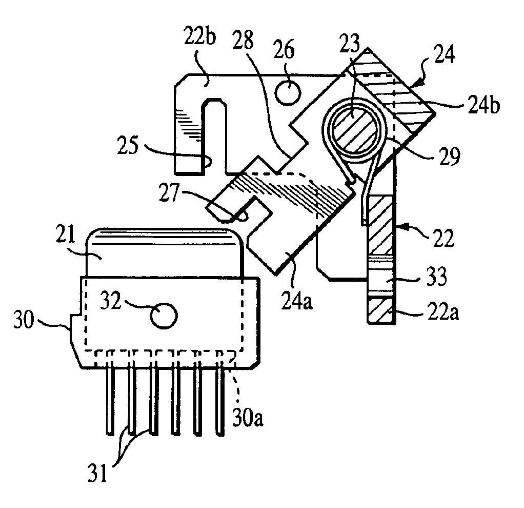
[0008]An object of the present invention is to provide a support structure for a magnetic head in which a magnetic head having a function of being capable of following a warp or the like of a magnetic card can be easily attached and detached without using a fastening member such as a screw.
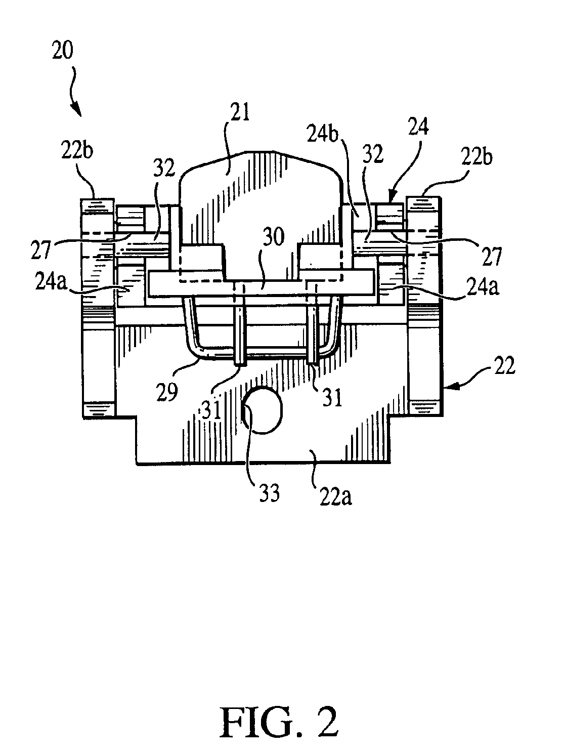
[0013]According to the present invention, when the movable member rotatably supported by the fixed member is rotated in the direction opposite to the fixed position against an urging force, since the support shafts at the side of the magnetic head can be attached to and detached from the groove portions, the magnetic head can be easily attached and detached without using a fastening member such as a screw.
[0016]According to the above structure, by the C-shaped structure of the movable member, it is possible to prevent the magnetic head from varying in the front-back direction of card transfer.

Problems solved by technology

However, in the support structure for the magnetic head of the conventional structure, since the magnetic head 96 is fitted by using the fastening member such as the screw 94, there have been problems, including that it is impossible to easily attach and detach the magnetic head 96 itself, and it is difficult to form a swing type magnetic head structural body into a unit.

Method used


Image

  • Support structure of a magnetic head and magnetic card reader
  • Support structure of a magnetic head and magnetic card reader
  • Support structure of a magnetic head and magnetic card reader

Examples


Embodiment Construction

[0031]An embodiment of the present invention will be described below in detail with reference to the drawings.

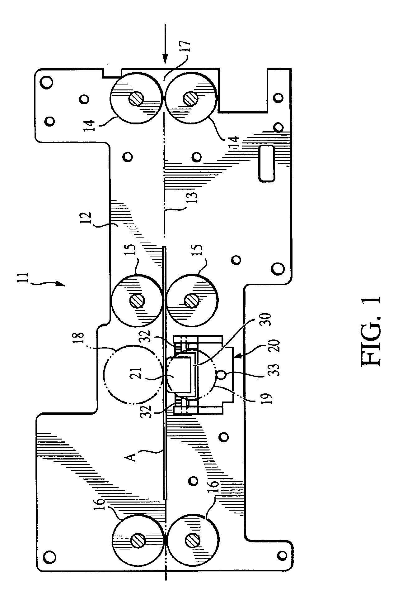
[0032]The drawings show a magnetic card reader including a support structure for a magnetic head, and in FIG. 1, this magnetic card reader 11 is constructed such that transfer rollers 14, 14, 15, 15, 16, 16 are provided at upper and lower opposite positions of a card transfer line 13 formed in a card reader main body 12, and a magnetic card A is reversibly transferred along the card transfer line 13 from an exit / inlet portion 17 of the magnetic card reader 11.

[0033]A press roller 18 and a transfer roller 19 are provided to be vertically opposite to each other between the foregoing transfer rollers 15 and 16, and a magnetic head unit 20 is provided at the side of the transfer roller 19, that is, the lower side of the card transfer line 13.

[0034]The magnetic head unit 20 includes a magnetic head 21, and is constructed such that reading, writing, and erasing of magnetic informa...


PUM

PropertyMeasurementUnit
structureaaaaaaaaaa
surface characteristicsaaaaaaaaaa
rotational movementaaaaaaaaaa

Abstract

There is provided a support structure for a magnetic head in which a magnetic head having a function of being capable of following a warp or the like of a magnetic card can be easily attached and detached without using a fastening member such as a screw. A support structure for a magnetic head for swingably supporting a magnetic head includes a fixed member fixed to a fixed portion, a movable member rotatably supported by the fixed member and urged toward a fixed position, and support shafts protrusively provided at the front and back of the magnetic head, in which groove portions for removably supporting the support shafts are formed at corresponding portions of the fixed member and the movable member in one of them in a vertical direction and in the other in a horizontal direction.

Description

BACKGROUND OF THE INVENTION[0001]1. Field of the Invention[0002]The present invention relates to a support structure for a magnetic head for reading out magnetic information from or writing it into a magnetic recording medium of a magnetic card, and a magnetic card reader.[0003]2. Description of the Related Art[0004]Conventionally, a support structure for a magnetic head is disposed in a magnetic card reader, for example, such as one shown in FIG. 12.[0005]That is, guide pins 92, 92 are provided at a fixed plate 91 provided at an apparatus main body side of a card reader, a movable plate 93 capable of moving vertically along the guide pins 92, 92 is provided, a magnetic head 96 is fitted to the movable plate 93 through a fastening member such as a screw 94 and a head holding bracket 95, and the magnetic head 96 is urged toward a side of a magnetic card 98 by urging means 97 such as a spring through the movable plate 93.[0006]According to this conventional structure, the magnetic hea...

Claims


Application Information

Patent Timeline
Patent Type & Authority Patents(United States)
IPC IPC(8): G11B5/49G11B5/58G11B21/20
CPCG11B5/49
Inventor NAKABO, AKINOBUOKADA, MASANOBU
Owner HITACHI CHANNEL SOLUTIONS CORP
Learn More