Opto-electronic oscillator including a tunable electro-optic filter

a technology of electro-optic filter and optoelectronic oscillator, which is applied in the direction of oscillator, laser details, instruments, etc., can solve the problems that the rf bandpass filter cannot provide for coarse frequency tuning and the rf bandpass filter cannot provide for fast tunability of the oeo's oscillation frequency

Inactive Publication Date: 2005-08-09
OEWAVES
View PDF26 Cites 70 Cited by
  • Summary
  • Abstract
  • Description
  • Claims
  • Application Information

AI Technical Summary

Problems solved by technology

One challenge associated with OEOs is that the OEO's RF bandpass filter can only provide for coarse frequency...

Method used


Image

  • Opto-electronic oscillator including a tunable electro-optic filter
  • Opto-electronic oscillator including a tunable electro-optic filter
  • Opto-electronic oscillator including a tunable electro-optic filter

Examples


Embodiment Construction

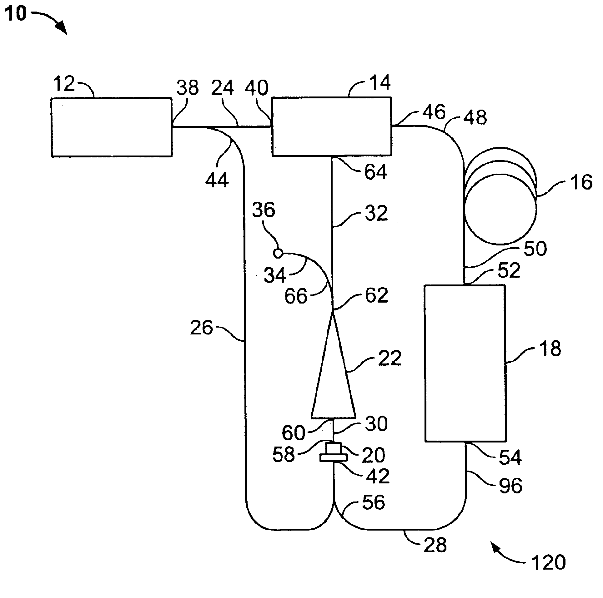
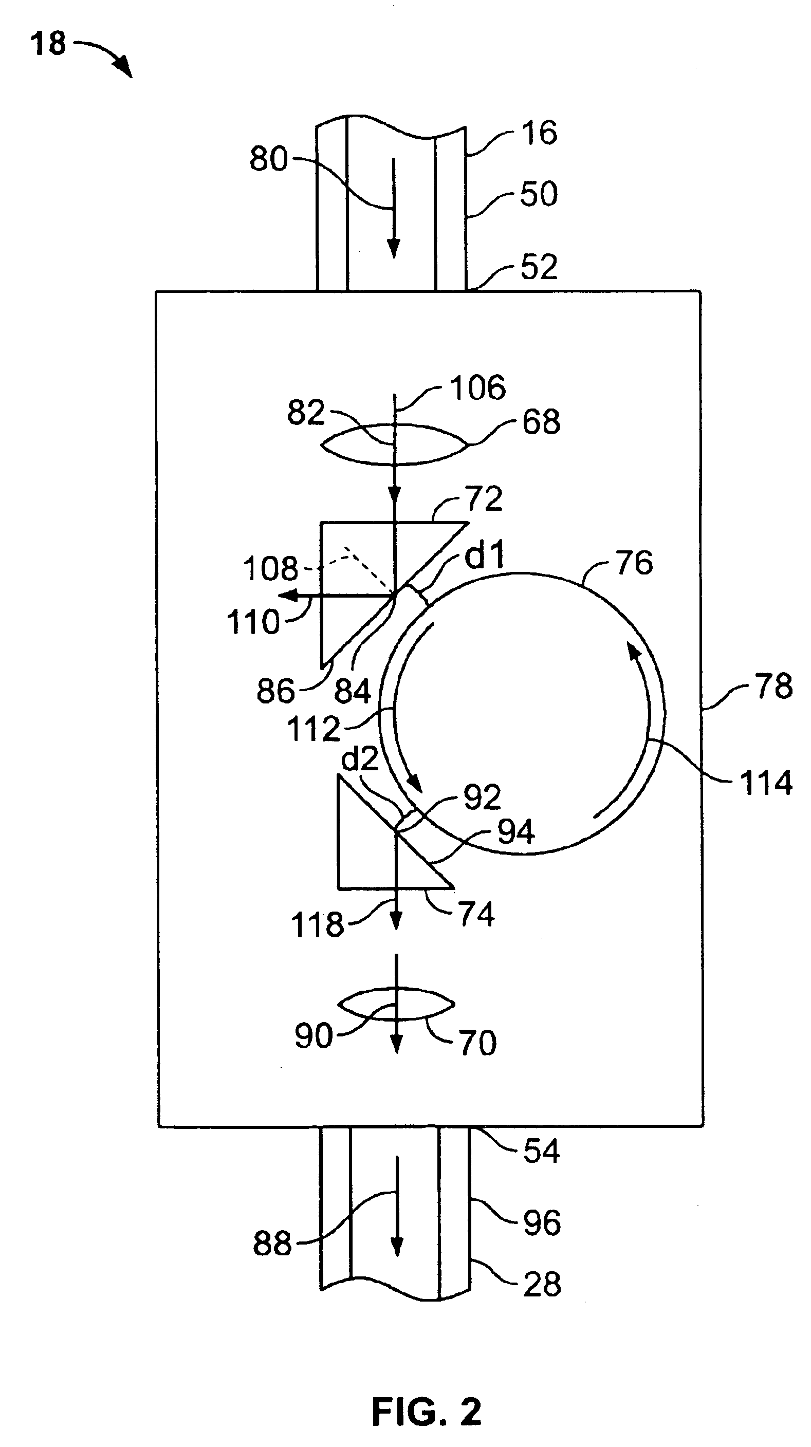
[0017]Optical resonators are electro-optical devices that are included in optical feedback loops to store energy having only specific resonant mode frequencies. Optical resonators are often small in size, having diameters on the order of millimeters, and may be used in many electro-optical system applications including tunable electro-optic filters. The optical resonators are curved optical waveguides, for example, a cylinder, a sphere, or a toroid within which light is internally reflected at the inner surface of the optical resonator.

[0018]Optical resonators can support resonator modes of light called whispering-gallery modes (“WGMs”), and thus, are often referred to as whispering-gallery mode resonators. WGMs occur when light having an evanescent wave component travels via internal reflection around the periphery of the optical resonator. The evanescent waves extend beyond the optical resonator's outer surface and may be coupled into an adjacent optical coupler as long as an opti...


PUM


Abstract

An opto-electronic oscillator including a modulator for outputting modulated light and a tunable filter for receiving modulated light output from the modulator.

Description

CROSS-REFERENCE TO RELATED APPLICATION[0001]The present application claims priority under 35 U.S.C. § 119(e) to U.S. Provisional application Ser. No. 60 / 325,351, filed on Sep. 26, 2001, which is expressly incorporated by reference in its entirety as though fully set forth herein.ORIGIN OF THE INVENTION[0002]The systems and techniques described herein were made in the performance of work under a contract issued by DARPA, and are subject to the provisions of Public Law 96-517 (35 U.S.C. § 202) in which the Contractor has elected to retain title. The U.S. Government has a paid-up license in this invention and the right in limited circumstances to require the patent owner to license others on reasonable terms as provided for by the terms of contract number DAAD17-02-C-0085 awarded by DARPA.FIELD OF THE INVENTION[0003]The present invention relates to opto-electronic systems, and in particular, to an opto-electronic oscillator including a tunable electro-optic filter.BACKGROUND OF THE INV...

Claims


Application Information

Patent Timeline
IPC IPC(8): G02B26/00G02F1/03G02F1/01G02F1/00H01S3/13H01S3/10H03B21/02H03B28/00H03C1/60
CPCH03B21/02H03B28/00H03C1/60H01S5/0085
Inventor MALEKI, LUTFOLLAHSARIRI, KOUROSILTCHENKO, VLADIMIR S.
Owner OEWAVES
Why Eureka
Try Eureka