Photoelectric oscillator

A technology of photoelectric oscillator and optical filter, applied in the field of communication

Active Publication Date: 2017-08-18
BEIJING UNIV OF POSTS & TELECOMM
View PDF5 Cites 17 Cited by
  • Summary
  • Abstract
  • Description
  • Claims
  • Application Information

AI Technical Summary

Problems solved by technology

[0005] The purpose of the embodiments of the present invention is to provide an optoelectronic oscillator to solve the technical problem of how to generate a periodic frequency-sweeping microwave signal with low phase noise, good period correlation and adjustable center frequency

Method used


Image

  • Photoelectric oscillator
  • Photoelectric oscillator
  • Photoelectric oscillator

Examples


Embodiment Construction

[0046] The following will clearly and completely describe the technical solutions in the embodiments of the present invention with reference to the accompanying drawings in the embodiments of the present invention. Obviously, the described embodiments are only some, not all, embodiments of the present invention. Based on the embodiments of the present invention, all other embodiments obtained by persons of ordinary skill in the art without making creative efforts belong to the protection scope of the present invention.

[0047] It should be noted that, in the case of no conflict, the technical contents in the various embodiments of the present invention can be combined with each other.

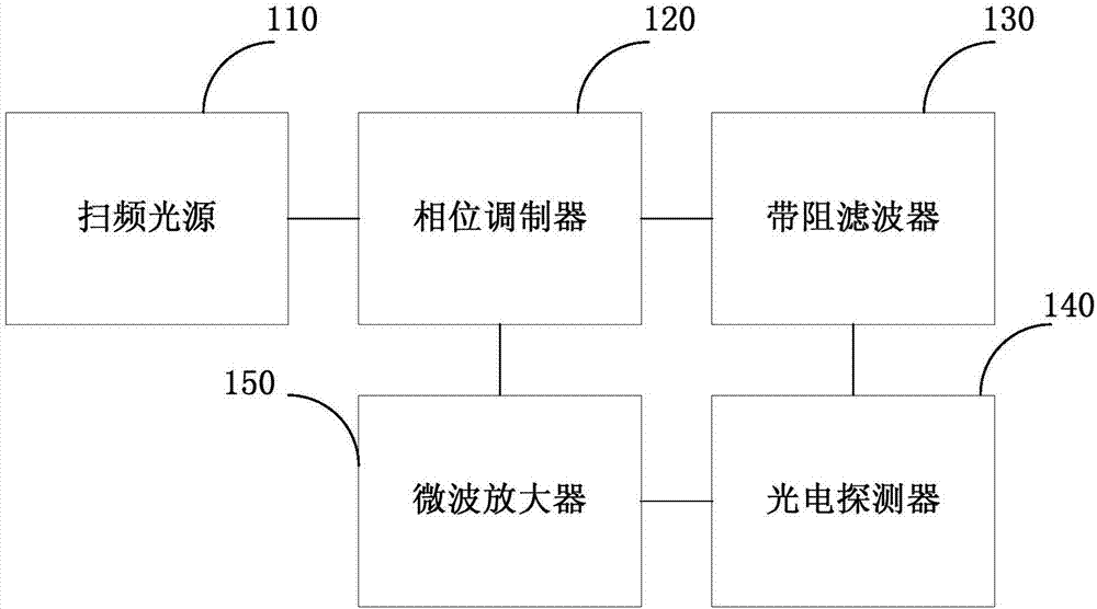
[0048] In order to solve the technical problem of how to generate a periodic frequency-sweeping microwave signal with low phase noise and an adjustable center frequency, an embodiment of the present invention provides an optoelectronic oscillator. Such asfigure 1 As shown, the optoelectronic o...


PUM


Abstract

The embodiment of the invention provides a photoelectric oscillator. The photoelectric oscillator comprises a swept source, a phase modulator and a band-stop optical filter. The phase modulator carries out phase modulation for a swept-frequency optical signal to generate a first intermediate signal with positive and negative first-order sidebands; the band-stop optical filter filters away any sideband in the first intermediate signal; the photoelectric detector is connected with the band-stop optical filter to receive an output signal of the band-stop optical filter, to convert the output signal into a periodic swept-frequency microwave signal with the central frequency adjustable and to feed the periodic swept-frequency microwave signal to the phase modulator after the periodic swept-frequency microwave signal is amplified; the swept source, the phase modulator and the band-stop optical filter compose a band-pass swept-frequency microwave filter; the central frequency of the band-pass swept-frequency microwave filter is equal to the difference between the central frequency of the swept source and the central frequency of the band-stop optical filter. Therefore, the embodiment of the invention solves the technical problem of how to generate the periodic swept-frequency microwave signal with low phase noise, good correlation and adjustable central frequency.

Description

technical field [0001] The invention relates to the technical field of communication, in particular to a photoelectric oscillator. Background technique [0002] Microwave signal sources have important applications in modern life, and are widely used in many fields such as communications, military radar, biological imaging, satellite positioning, and scientific measurement. The effective and accurate operation of the above systems is closely related to the quality of microwave signals. Especially in military radar and scientific metrology, higher requirements are placed on the signal quality. In order to obtain high-frequency microwave signals, frequency doubling technology is usually used to double the frequency of low-frequency signals to high frequencies. However, frequency doubling technology will make the signal noise deterioration at least 20log10(N), where N is the frequency multiplication coefficient. Therefore, in order to obtain high-quality microwave signals, it ...

Claims


Application Information

Patent Timeline
Patent Type & Authority Applications(China)
IPC IPC(8): H01S1/02
CPCH01S1/02
Inventor 戴一堂岑启壮徐坤
Owner BEIJING UNIV OF POSTS & TELECOMM
Why Eureka
Try Eureka