High-resolution three-dimensional imaging radar

a three-dimensional imaging and high-resolution technology, applied in the field of high-frequency real-time aperture three-dimensional radar imaging systems, can solve the problem of near perfectly bandwidth-limited range resolution of detected signals, and achieve the effect of high signal power

Active Publication Date: 2008-12-11
CALIFORNIA INST OF TECH
View PDF16 Cites 51 Cited by
  • Summary
  • Abstract
  • Description
  • Claims
  • Application Information

AI Technical Summary

Benefits of technology

[0018]Embodiments of the invention are directed to a three-dimensional imaging radar operating at high frequency, e.g. 670 GHz. At such high frequencies, centimeter-scale spatial resolution in three dimensions is possible without excessively large fractional bandwidths or aperture sizes. The active target illumination inherent in radar ensures high signal power provides for spectroscopic flexibility. A submillimeter imaging radar may use low phase-noise synthesizers and a fast microwave chirp-generator to produce a frequency-modulated continuous-wave (FMCW) wave

Problems solved by technology

A complete digital signal processor system may be used for performing chirp-nonlinearity compensation, fast Fourier transform (FFT), peak detection, and signal proc

Method used


Image

  • High-resolution three-dimensional imaging radar
  • High-resolution three-dimensional imaging radar
  • High-resolution three-dimensional imaging radar

Examples


Embodiment Construction

[0040]1. Overview

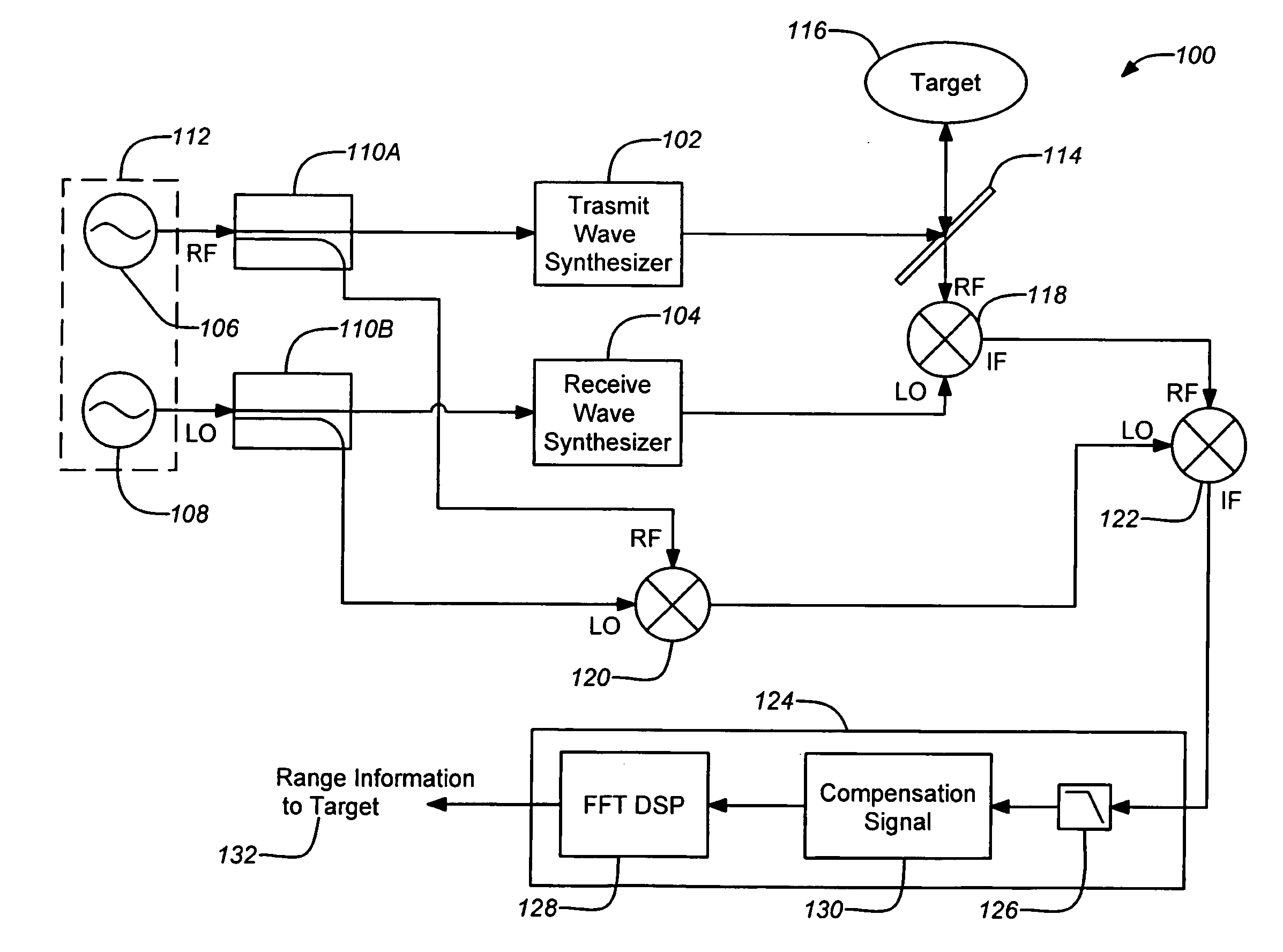
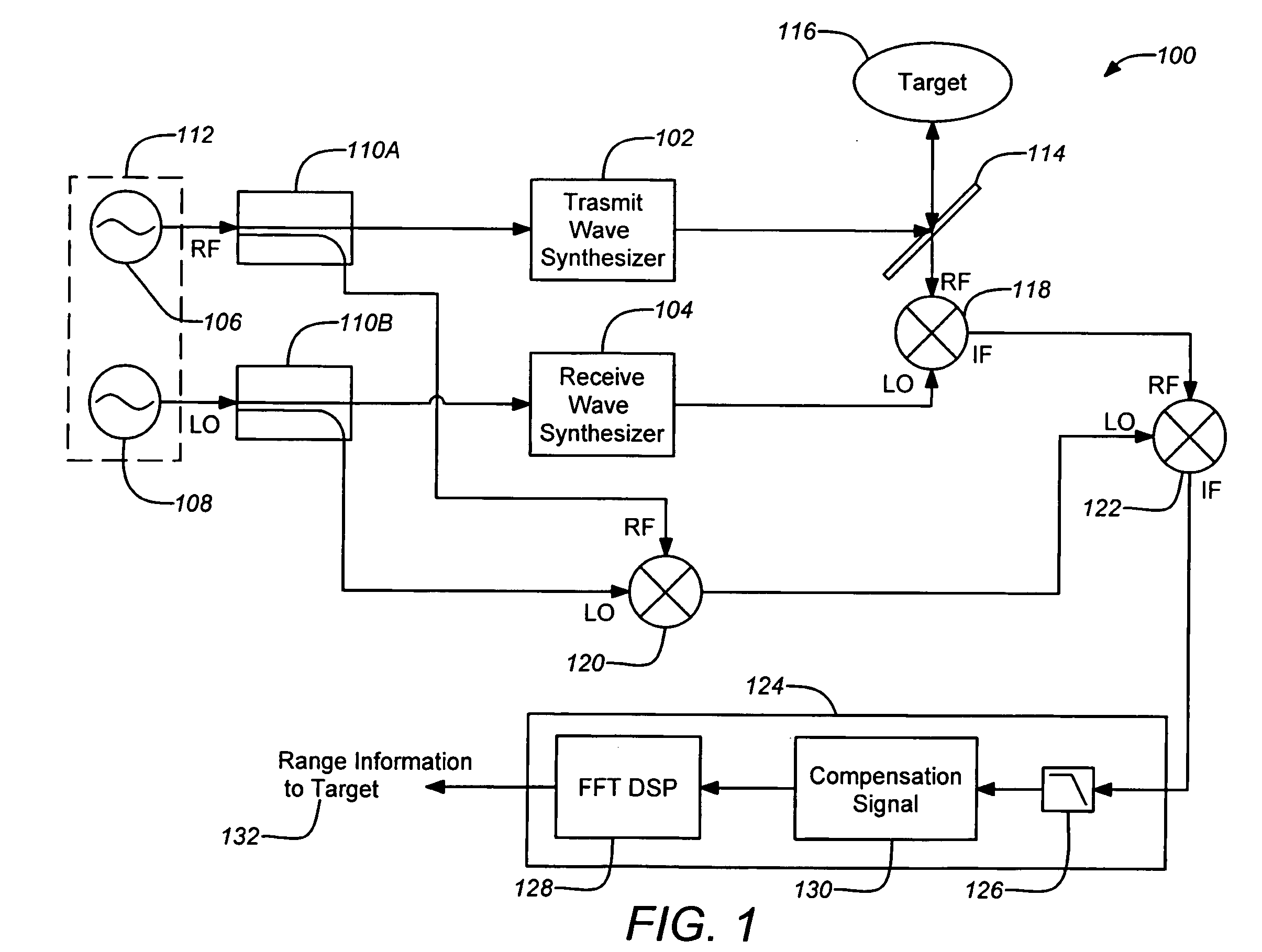
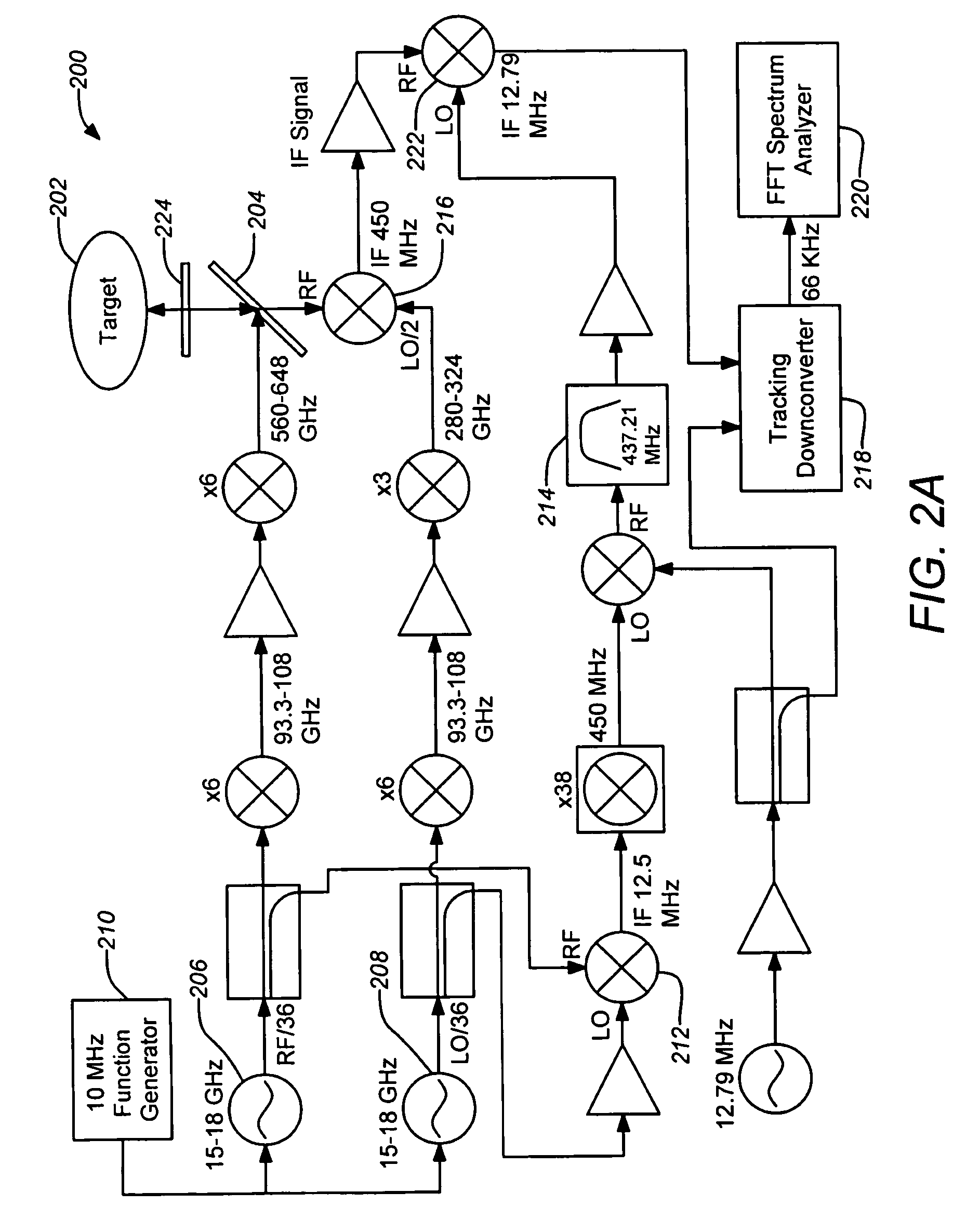
[0041]An imaging radar is described that operates at submillimeter wavelengths for applications ranging from concealed weapons detection to planetary trace-chemical identification. Unlike conventional radars, which typically operate below 100 GHz (i.e., wavelengths greater than approximately 3 mm), a system operating well above this, e.g., 670 GHz, is capable of very high imaging resolution in three dimensions because since its high modulation bandwidth gives higher range resolution and its shorter wavelength gives higher lateral image resolution for any fixed antenna aperture size. Using a novel signal generation architecture, the submillimeter radar is capable of quickly, quietly, and linearly frequency-sweep over a bandwidth of 18 GHz, thus permitting an ultra-high range resolution of less than 1 cm. With an aperture size of 50 cm, the radar is also able to resolve targets within 2 cm at stand-off distances of 25 m. In addition, the submillimeter radar is novel b...


PUM


Abstract

A three-dimensional imaging radar operating at high frequency e.g., 670 GHz, is disclosed. The active target illumination inherent in radar solves the problem of low signal power and narrow-band detection by using submillimeter heterodyne mixer receivers. A submillimeter imaging radar may use low phase-noise synthesizers and a fast chirper to generate a frequency-modulated continuous-wave (FMCW) waveform. Three-dimensional images are generated through range information derived for each pixel scanned over a target. A peak finding algorithm may be used in processing for each pixel to differentiate material layers of the target. Improved focusing is achieved through a compensation signal sampled from a point source calibration target and applied to received signals from active targets prior to FFT-based range compression to extract and display high-resolution target images. Such an imaging radar has particular application in detecting concealed weapons or contraband.

Description

CROSS-REFERENCE TO RELATED APPLICATIONS[0001]This application claims the benefit under 35 U.S.C. §119(e) of the following U.S. provisional patent applications, which are both incorporated by reference herein:[0002]U.S. Provisional Patent Application No. 60 / 933,382, filed Jun. 6, 2007, and entitled “600 GHZ HIGH-RESOLUTION RADAR”, by Cooper et al. (Attorney Docket CIT-4898-P); and[0003]U.S. Provisional Patent Application No. 60 / 959,301, filed Jul. 12, 2007, and entitled “600 GHZ HIGH-RESOLUTION RADAR”, by Cooper et al. (Attorney Docket CIT-4898-P2).STATEMENT OF GOVERNMENT RIGHTS[0004]The invention described herein was made in the performance of work under a NASA contract, and is subject to the provisions of Public Law 96-517 (35 U.S.C. 202) in which the Contractor has elected to retain title.BACKGROUND OF THE INVENTION[0005]1. Field of the Invention[0006]This invention relates to imaging radar systems. Particularly, this invention relates to high frequency real aperture three-dimensi...

Claims


Application Information

Patent Timeline
IPC IPC(8): G01C3/08
CPCG01S13/34G01S13/887G01S13/89
Inventor COOPER, KEN B.CHATTOPADHYAY, GOUTAMSIEGEL, PETER H.DENGLER, ROBERT J.SCHLECHT, ERICH T.MEHDI, IMRANSKALARE, ANDERS J.
Owner CALIFORNIA INST OF TECH
Why Eureka
Try Eureka