Method for determining the spectral scale of a spectrometer and apparatus

A spectral calibration and spectral intensity technology, applied in the field of devices, can solve the problem of low signal power

Active Publication Date: 2017-05-17
SPECTRAL ENGINES
View PDF9 Cites 4 Cited by
  • Summary
  • Abstract
  • Description
  • Claims
  • Application Information

AI Technical Summary

Problems solved by technology

Therefore, very narrow transmission peaks located relatively close to each other can increase calibration time

Method used


Image

  • Method for determining the spectral scale of a spectrometer and apparatus
  • Method for determining the spectral scale of a spectrometer and apparatus
  • Method for determining the spectral scale of a spectrometer and apparatus

Examples


Embodiment Construction

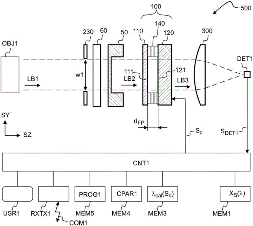
[0065] refer to figure 1 , the spectrometer 500 may include a Fabry-Perot interferometer 100 and a detector DET1. Object OBJ1 may reflect, emit and / or transmit light LB1. Light LB1 may be coupled into spectrometer 500 to monitor the spectrum of light LB1.

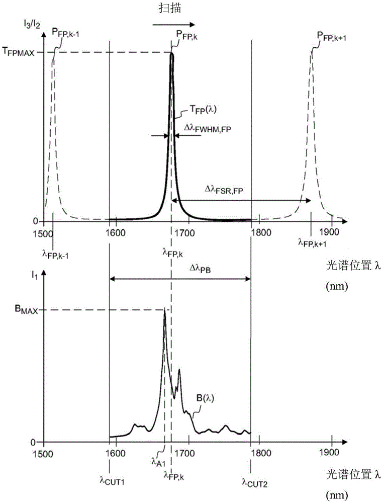
[0066] The Fabry-Perot interferometer 100 includes a first half mirror 110 and a second half mirror 120 . The distance between the first mirror 110 and the second mirror 120 is equal to the mirror gap d FP . Mirror gap d FP Can be adjustable. The first mirror 110 may have a solid-air interface 111 and the second mirror 120 may have a solid-air interface 121 . Mirror gap d FPThe distance between interfaces 111 and 121 may be represented. The Fabry-Perot interferometer 100 provides the transmission peak P FP,k ( figure 2 ), where the transmission peak P FP,k The spectral position of can depend on the mirror gap d FP . Transmission peak P FP,k The spectral position of can be changed by changing the mirror spacin...


PUM


Abstract

A method for determining spectral calibration data ([lambda]cal(Sd), Sd, cal(lambda)) of a Fabry-Perot interferometer (100) comprises: forming a plurality of filtered spectral peaks (P1, P2) by filtering input light (LB1) with a Fabry-Perot etalon (50) such that a first filtered peak (P1) corresponds to a first transmittance peak (P1) of the etalon (50), and such that a second filtered peak (P2) corresponds to a second transmittance peak (P2) of the etalon (50), using the Fabry-Perot interferometer (100) for measuring a spectral intensity distribution (M(Sd)) of the filtered spectral peaks (P1, P2), wherein the spectral intensity distribution (M(Sd)) is measured by varying the mirror gap (dFP) of the Fabry-Perot interferometer (100), and by providing a control signal (Sd) indicative of the mirror gap (dFP), and determining the spectral calibration data ([lambda]cal(Sd), Sd, cal(lambda)) by matching the measured spectral intensity distribution (M(Sd)) with the spectral transmittance (TE(lambda)) of the etalon (50).

Description

technical field [0001] The invention relates to a method for determining spectral calibration data of a Fabry-Perot interferometer. Some variations involve spectral analysis of light. Furthermore, the invention relates to a device. Background technique [0002] The wavelength scale of the Fabry-Perot interferometer can be calibrated, for example, by measuring the excitation spectrum of a gas discharge lamp. Gas discharge lamps may generally contain, for example, argon, neon, xenon, krypton, hydrogen or mercury. The spectrum of a gas discharge lamp includes a large number of atomic emission lines, which are characteristic of the gas contained in the lamp. However, gas discharge lamps are not efficient for all useful wavelength regions. The spectral separation between atomic lines can sometimes be too narrow for accurate calibration. The spectral separation between atomic spectral lines can sometimes be too large for accurate calibration. The calibration lamp consumes el...

Claims


Application Information

Patent Timeline
IPC IPC(8): G01J3/26G02B26/00G02B5/28G01J3/28G02F1/21
CPCG01J3/26G01J3/28G02B26/001G01J3/0227G01J3/0286G01J3/0264G01J3/027G01J3/0297G01J3/45G01J2003/2879
Inventor 亚尔科·安蒂拉尤拉·坎托加维阿提·阿库亚为弥可·突海涅米亚斯·马科耶恩
Owner SPECTRAL ENGINES
Why Eureka
Try Eureka