LC oscillator with wide tuning range and low phase noise

a phase locked loop, voltage-controlled technology, applied in the direction of pulse generator, pulse technique, electrial characteristics varying frequency control, etc., can solve the problems of generic integer-n frequency synthesizers that cannot be used, circuit area, power consumption,

Inactive Publication Date: 2005-04-05
GCT SEMICONDUCTOR INC
View PDF8 Cites 49 Cited by
  • Summary
  • Abstract
  • Description
  • Claims
  • Application Information

AI Technical Summary

Benefits of technology

Additionally, embodiments of the present invention provide a method for tuning an oscillator circuit, the method comprising: providing a bias voltage via a resistor to a reactive element so that the reactive element has a bias voltage when a first switch is open; and using the first switch to couple and decouple the reactive element from the oscillator, thereby adjusting the frequency of the oscillator.

Problems solved by technology

The common factors are circuit area, cost, and power consumption.
However, in General Packet Radio Service (GPRS) applications, the generic integer-N frequency synthesizer cannot be used, because a lock time of less than 150 μs is required.
The VCO 208 is a sensitive device, and its phase noise performance characteristic may be greatly affected by environmental conditions such as power supply variation, temperature and noise.
Since the phase noise specification in mobile phone applications is so stringent, the allowable types of the VCO are limited, and an LC oscillator is usually used.
However, since the formation of a variable inductor is not easy, a variable capacitor can be used for controlling the frequency of the VCO.
But this approach leads to large circuit area and high cost.
The most difficult factor in the design of a fully integrated LC oscillator is to guarantee stable operation against process and environmental variations.
However, the wide tuning range conflicts with the design goal of small gain in order to achieve low phase noise characteristics.
When an initial bias condition of such a floated terminal is too high or low, it can greatly affect the device reliability.
Where the offset voltage is excessive, the switches may be damaged, and the reliability of the VCO may be degraded.
Since this kind of parasitic junction has a very poor quality factor, the phase noise performance in this case will be severely degraded.

Method used


Image

  • LC oscillator with wide tuning range and low phase noise
  • LC oscillator with wide tuning range and low phase noise
  • LC oscillator with wide tuning range and low phase noise

Examples


Embodiment Construction

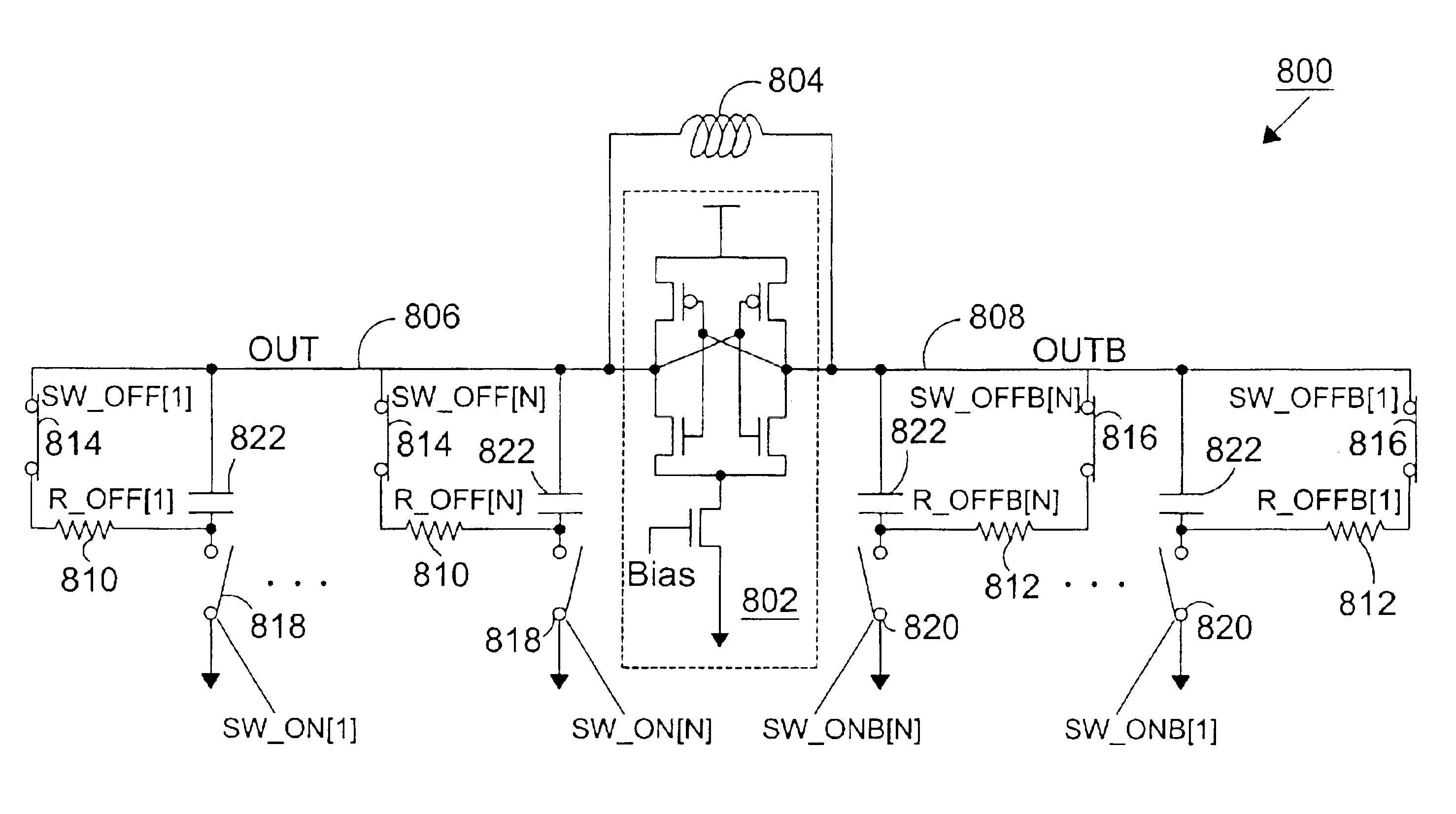
FIG. 6 is a block diagram illustrating an embodiment of the invention. An oscillator circuit 600 includes an oscillator 610 and at least one adjusting circuit 620 operably coupled to the oscillator 610. The adjusting circuit includes a biasing resistor 622, a reactive element 624 (e.g., a capacitor) and a first switch 626. The first switch 626 selectively couples and decouples the reactive element 624 from the oscillator circuit 600. The biasing resistor 622 provides a bias voltage VA to the reactive element 624 so that the reactive element 624 has a bias voltage when the first switch 626 is open.

As discussed in detail in the following sections, the bias voltage VA can be supplied to the reactive element in a variety of configurations. For example, a biasing switch 628 can be located between the bias resistor 622 and the bias voltage VA. The bias switch 628 selectively couples the bias resistor 622 to the bias voltage when the first switch 626 decouples the reactive element 624. The...


PUM


Abstract

A voltage-controlled oscillator including an active oscillator circuit, an inductor, and capacitive circuits is disclosed. The capacitive circuits are selectively turned on and off to control the frequency of the voltage-controlled oscillator. Particularly, the inductor and the capacitors in the capacitive circuits form LC circuits that provide feedback to the active oscillator circuit. To avoid damage to the switches in the capacitive circuits, the capacitive circuits further comprise resistors. The resistors can be configured in several different ways so that the voltage-controlled oscillator can have a high degree of reliability, and a wide tuning range with constant phase noise performance.

Description

BACKGROUND OF THE INVENTION1. Field of the InventionThe invention relates generally to the field of wireless communications, and more particularly to a voltage-controlled oscillator of a phase locked loop circuit.2. Background of the Related ArtPhase Locked Loops (PLLs) have wide application in areas such as wireless communications systems and other products. In many applications, the PLL has very stringent performance requirements. There can be more than one PLL circuit 110, 120 in a typical wireless system. For example, a typical block diagram of a receiver using a super-heterodyne architecture 100 is shown in FIG. 1. Those skilled in the art will readily recognize the various blocks and their functions, so a detailed recitation of the block diagram will not be further described herein.PLLs used in wireless communication systems provide a highly stable carrier signal for the modulation and the demodulation processes. The carrier signal should have sufficient spectral purity (often...

Claims


Application Information

Patent Timeline
Patent Type & Authority Patents(United States)
IPC IPC(8): H03B5/08H03B5/12H03B1/00H03L7/099
CPCH03B5/1265H03B5/1228H03B5/1215H03L7/099H03B2201/025H03J2200/10H03B5/08
Inventor KOO, YIDOLEE, JEONG-WOOPARK, JOONBAELEE, KYEONGHO
Owner GCT SEMICONDUCTOR INC
Why Eureka
Try Eureka